
It does, but of course the key is long broken.
It'd be easy to accomplish if my mirror control was in the door, but alas it's not.
So I need to find the two wires that fire the cl solenoids as they pass through the interior of the car.
A.
Congratulations to vtecmec for winning May/June's Lude Of The Month, with his DIY Turbo BB1 build.
>>> Click Here For Profile <<<

>>> Click Here For Profile <<<
Folding mirrors/central locking - How to!
-
wurlycorner

- Ye are glad to be dead, RIGHT?
- Posts: 21511
- Joined: Sat May 19, 2012 3:33 pm
- My Generation: 4G
- Location: Chelmsford, Essex
- Has thanked: 2507 times
- Been thanked: 317 times
How to connect folding mirrors to central locking.
I've been mulling about this for ages. The instructions from another site state that you can pick up the door lock circuits 'above the fuse box' but I couldn't find the wires there. And you have to take the centre console apart to connect to the mirror retract button.
Then it struck me that there was a Better Way (there's always a Better Way), for those of us with facelift 4Gs which have the mirror control in the centre, not the driver's door.
The mirror control box is in the passenger door! And the passenger door has a lock! So all the wires necessary are right there, in the door. No need to forage about in the centre console or the dash loom.
Here's what I did:
Remove door card, locate loom attached to the mirror control box, which is beneath the mirror. Locate the wire that comes from the mirror fold button, which is the blue/yellow one:
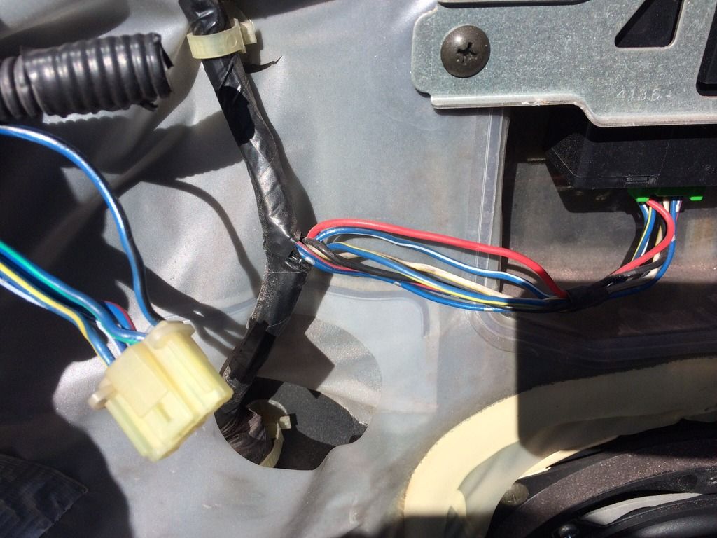
The plug shown there is the one which goes to the window switch, of which more anon.
Then locate the two wires that go to the door lock solenoid, which is easy since they connect to a plug near the back of the door. Yellow/red and white/red. You'll see it.
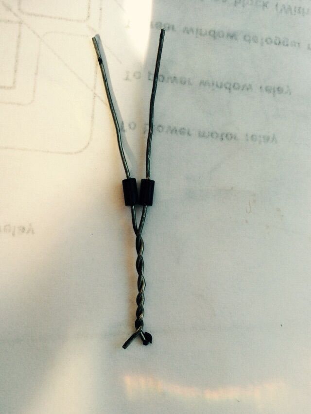
Make up a pair of diodes, cathode (white band) to cathode. The type can be 1N4001 or similar. Pence. The cathodes will connect to the blue/yell wire to fire the mirrors, the separate anodes will connect to the lock wires.
A diode is a device that allows current to flow one way only. You need these because without them, the circuit would work in reverse, in that if you manually retracted the mirrors it would lock the doors. Also, the diodes connect the two wires going to the lock solenoid one way, but keep them isolated the other way.
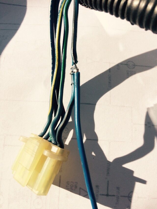
Here are the diodes:
And after soldering and heat-shrinking:
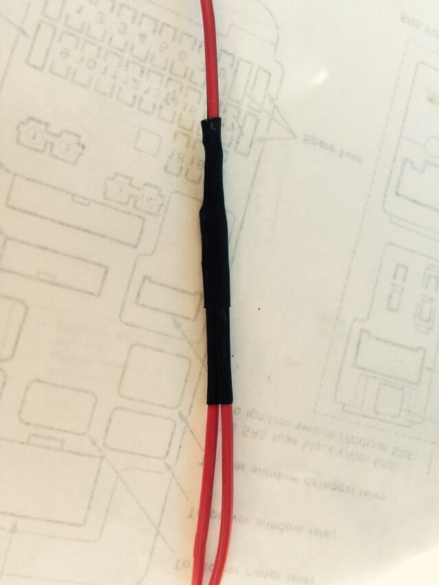
As you can see I'd soldered some tails to the diodes, to make connecting easier. The one from the common cathodes is about 30cm long, the other two only about 5cm.
Then I connected the two anode wires to the lock solenoid wires. I don't like using Scotchloks, they tend to corrode and fail, so I prefer to solder. You can use Scotchloks at your own risk though of you're not a solderer!
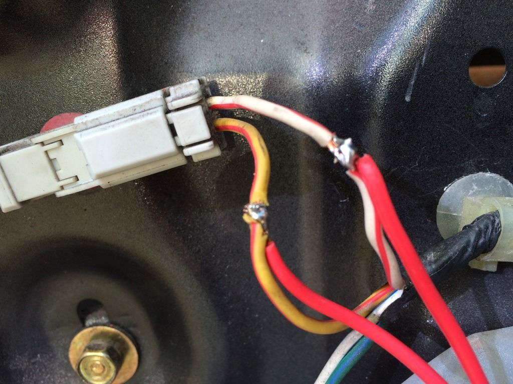
Obviously I insulated with tape afterwards.
The common cathode wire is then run along the loom and connected straight to the blue/yellow on the mirror control box, again by Scotchlok or soldering.
And if you're simple and straightforward, Bob is your proverbial.
However, if you're an awkward sod like me, you have an alarm which locks the doors when you drive away. That's fine and dandy, except with only the preceding implementation the mirrors would then retract. Which is not a Good Thing.
So I installed a relay to prevent this.
The idea is that the relay has a normally-closed contact, which opens when IGN is present. So when the car is off, the relay passes the signal to the mirror control and unfolds the mirrors. However once the car is started, the relay energises and disconnects the feed from the door lock solenoids to the mirror control, so nothing happens.
You need an automotive relay with a normally-closed contact. This means five terminals. Unfortunately the one I had, had only four terminals - so I had to modify it to provide the normally-closed contact. But less of that.
I picked up an IGN positive from the window loom which is right next to the mirror control loom. The black/blue wire goes +ve when IGN is on.
So I connected a wire to this, and to the black of the mirror control loom, which is negative. These two wires go to the coil terminals of the relay, shown on the diagram on the relay as a little rectangle. Then the wire from the lock solenoids via the diodes goes first to the common switch contact of the relay (contact '30'), then from the normally-closed contact ('87a') to the mirror control wire as before:
(Again, the connection was insulated with tape afterwards. You could use a Scotchlok).
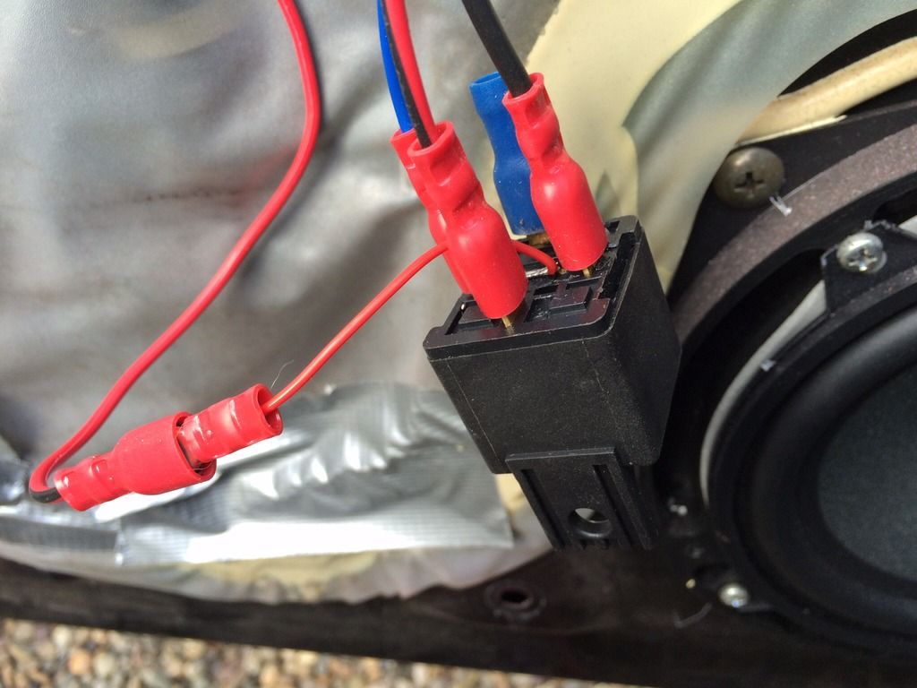
Here's a pic of the relay with the wires attached, the thin red is the modification I made to the relay because I'd bought the wrong type, and the blue connector is just put there to insulate the unused normally-open relay terminal:
I then mounted this relay beside the mirror control box, it fits perfectly:
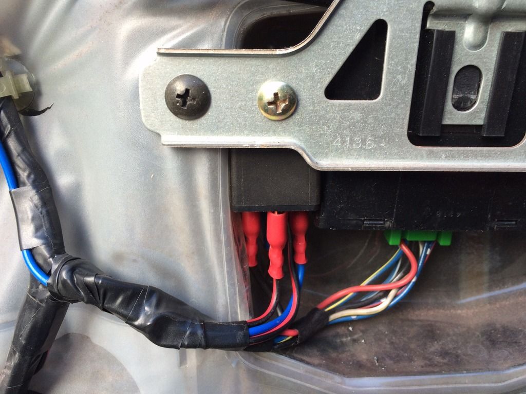
And that's it! Reassemble the door card, and show your afternoon's accomplishment to your unimpressed other half!
For the techie amongst us, here's the modifications to the door lock and mirror control circuitry, excluding the relay:
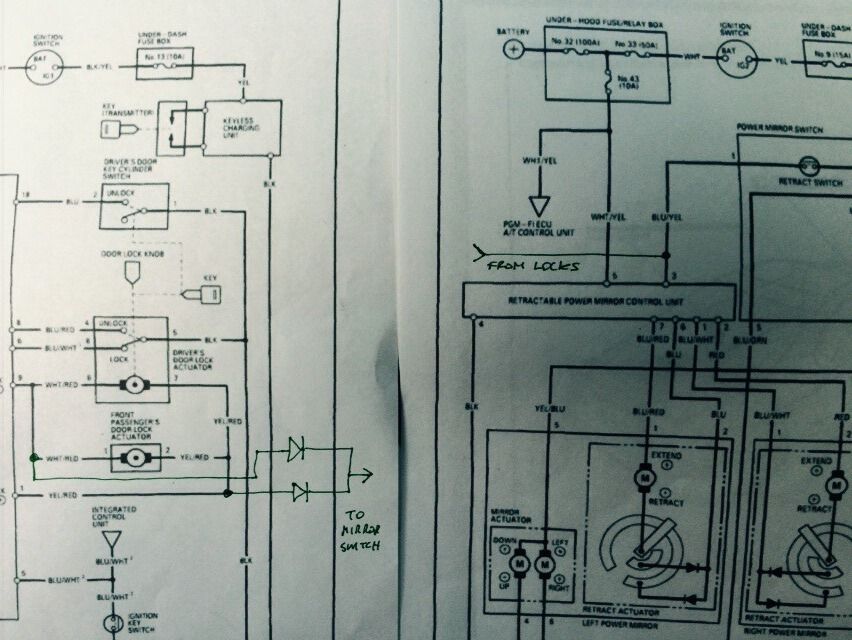
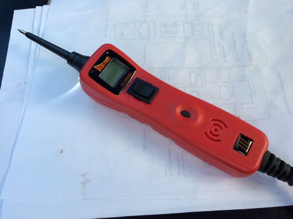
…and if you're doing various electrical work to your car, and you haven't got one of these, a Power Probe, get one, it's invaluable!
And here's the resultant magic:
https://youtu.be/5XSM8lvfZy0
A.
Then it struck me that there was a Better Way (there's always a Better Way), for those of us with facelift 4Gs which have the mirror control in the centre, not the driver's door.
The mirror control box is in the passenger door! And the passenger door has a lock! So all the wires necessary are right there, in the door. No need to forage about in the centre console or the dash loom.
Here's what I did:
Remove door card, locate loom attached to the mirror control box, which is beneath the mirror. Locate the wire that comes from the mirror fold button, which is the blue/yellow one:
The plug shown there is the one which goes to the window switch, of which more anon.
Then locate the two wires that go to the door lock solenoid, which is easy since they connect to a plug near the back of the door. Yellow/red and white/red. You'll see it.
Make up a pair of diodes, cathode (white band) to cathode. The type can be 1N4001 or similar. Pence. The cathodes will connect to the blue/yell wire to fire the mirrors, the separate anodes will connect to the lock wires.
A diode is a device that allows current to flow one way only. You need these because without them, the circuit would work in reverse, in that if you manually retracted the mirrors it would lock the doors. Also, the diodes connect the two wires going to the lock solenoid one way, but keep them isolated the other way.
Here are the diodes:
And after soldering and heat-shrinking:
As you can see I'd soldered some tails to the diodes, to make connecting easier. The one from the common cathodes is about 30cm long, the other two only about 5cm.
Then I connected the two anode wires to the lock solenoid wires. I don't like using Scotchloks, they tend to corrode and fail, so I prefer to solder. You can use Scotchloks at your own risk though of you're not a solderer!
Obviously I insulated with tape afterwards.
The common cathode wire is then run along the loom and connected straight to the blue/yellow on the mirror control box, again by Scotchlok or soldering.
And if you're simple and straightforward, Bob is your proverbial.
However, if you're an awkward sod like me, you have an alarm which locks the doors when you drive away. That's fine and dandy, except with only the preceding implementation the mirrors would then retract. Which is not a Good Thing.
So I installed a relay to prevent this.
The idea is that the relay has a normally-closed contact, which opens when IGN is present. So when the car is off, the relay passes the signal to the mirror control and unfolds the mirrors. However once the car is started, the relay energises and disconnects the feed from the door lock solenoids to the mirror control, so nothing happens.
You need an automotive relay with a normally-closed contact. This means five terminals. Unfortunately the one I had, had only four terminals - so I had to modify it to provide the normally-closed contact. But less of that.
I picked up an IGN positive from the window loom which is right next to the mirror control loom. The black/blue wire goes +ve when IGN is on.
So I connected a wire to this, and to the black of the mirror control loom, which is negative. These two wires go to the coil terminals of the relay, shown on the diagram on the relay as a little rectangle. Then the wire from the lock solenoids via the diodes goes first to the common switch contact of the relay (contact '30'), then from the normally-closed contact ('87a') to the mirror control wire as before:
(Again, the connection was insulated with tape afterwards. You could use a Scotchlok).
Here's a pic of the relay with the wires attached, the thin red is the modification I made to the relay because I'd bought the wrong type, and the blue connector is just put there to insulate the unused normally-open relay terminal:
I then mounted this relay beside the mirror control box, it fits perfectly:
And that's it! Reassemble the door card, and show your afternoon's accomplishment to your unimpressed other half!
For the techie amongst us, here's the modifications to the door lock and mirror control circuitry, excluding the relay:
…and if you're doing various electrical work to your car, and you haven't got one of these, a Power Probe, get one, it's invaluable!
And here's the resultant magic:
https://youtu.be/5XSM8lvfZy0
A.
Last edited by alinton on Sun Sep 20, 2015 11:20 pm, edited 1 time in total.
---------------------
'96 BB4.
'96 BB4.
-
wurlycorner
- Ye are glad to be dead, RIGHT?
- Posts: 21511
- Joined: Sat May 19, 2012 3:33 pm
- My Generation: 4G
- Location: Chelmsford, Essex
- Has thanked: 2507 times
- Been thanked: 317 times