BUILD PART 5) – Build – Battery Relocation + PAS removal
Forgot to update my thread on here!
PART 5) – Build (Continued)
Battery Relocation
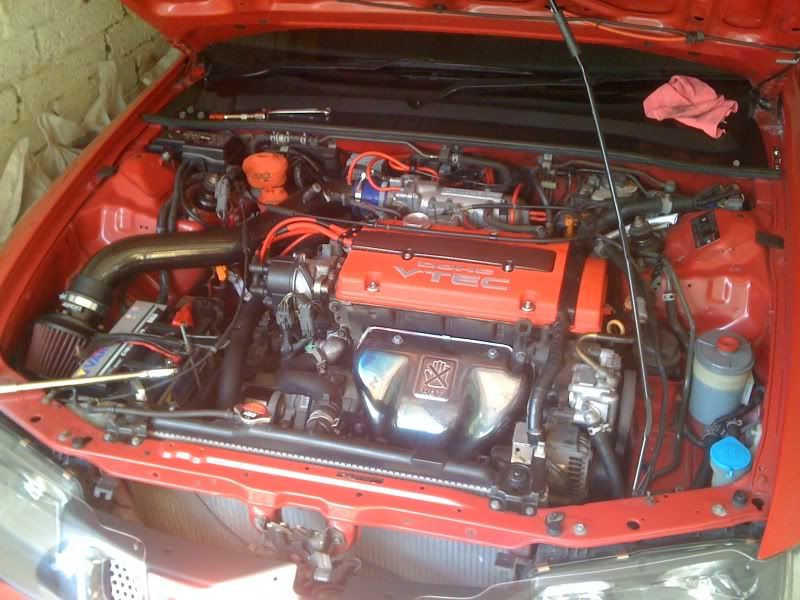
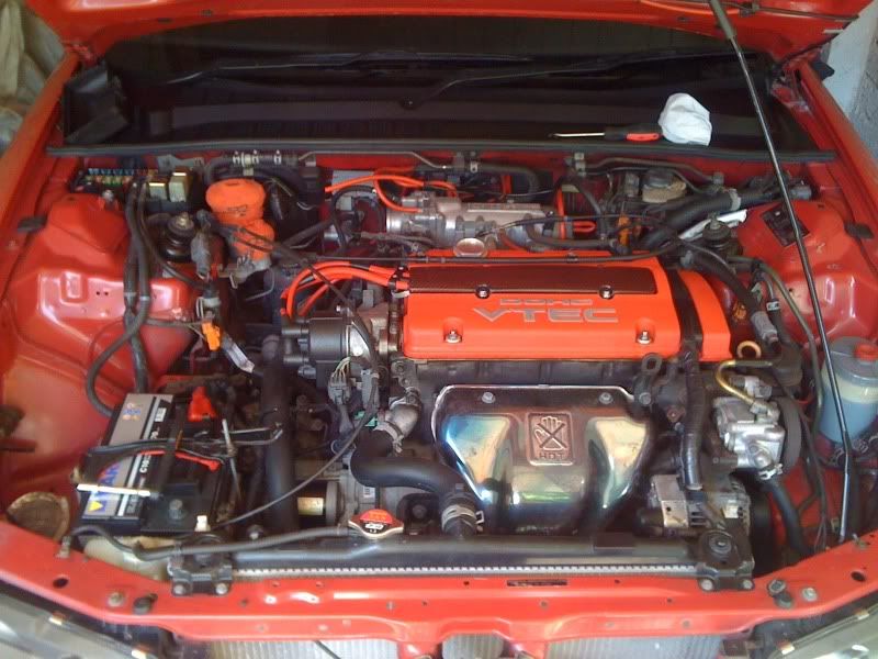
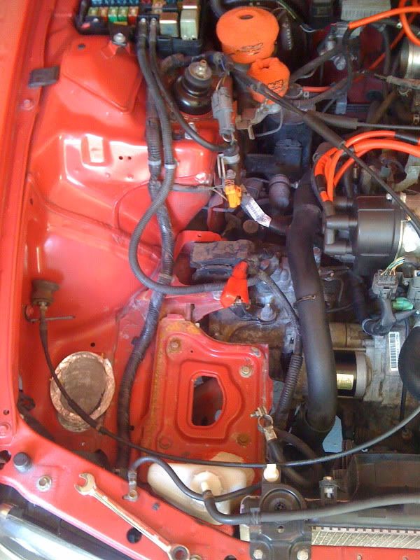
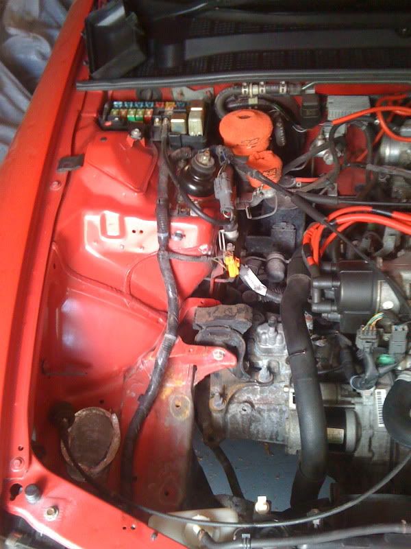
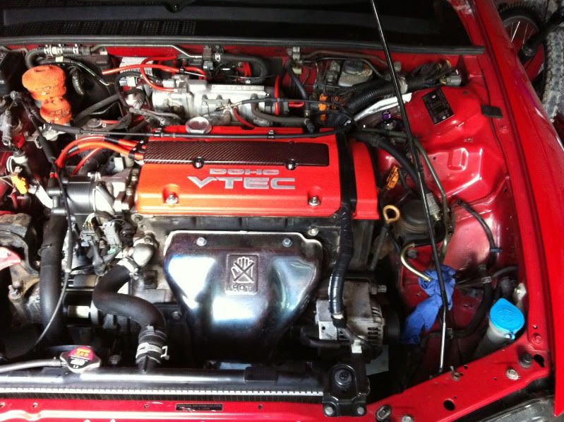
I found an afternoon where I was free to start the battery relocation. So here we go, engine bay when I started:
Already sold the crome battery cover to Mercutio – so assume Bri has it now?

Decided to remove the front bumper and intake at this point too – looking worse for wear:


Battery removed:
Little bit rusty on the battery tray because mine has never had a plastic tray to sit on. Lasted quite well really then!
Now remove the four bolts holding the tray to the frame and support – 4 x 12mm from memory? And remove tray:
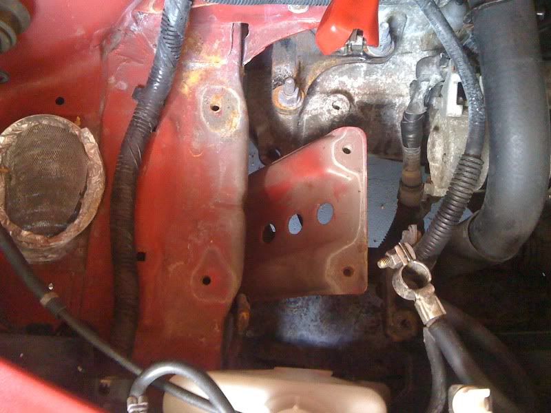
Now remove two further bolts that secure the support to the side of the frame – 2 x 12mm? And remove support:

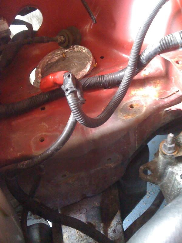
From here I decided to remove some of the power / earth wiring, but would be leaving any more for another day. If you’re not familiar with the wiring then make sure you rewire at the same point as you don’t want to forget anything!
I removed:
- Power wire to engine bay fusebox from battery
- Power wire to starter from battery
- Earth wire to front radiator stay part of frame – above drivers headlight to battery
- Earth wire from bracket on gearbox to battery
Pics:
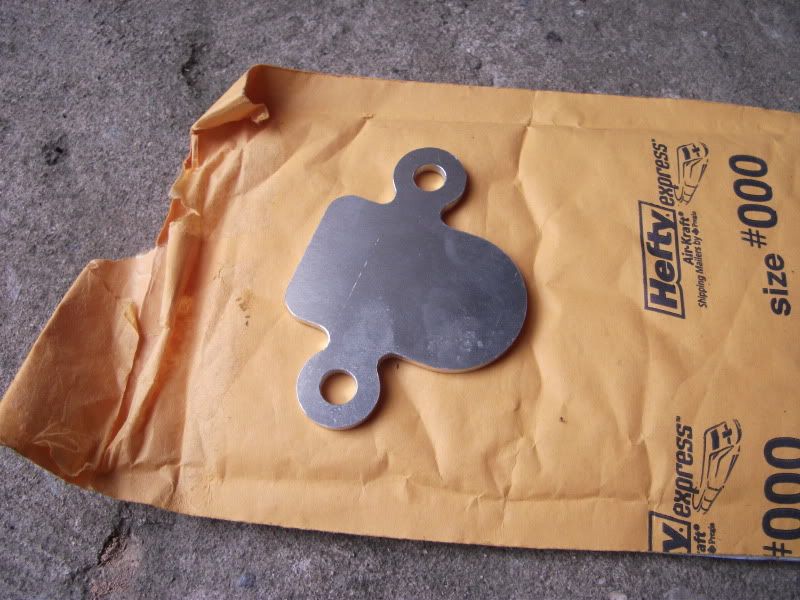
When I move onto the new wiring and battery mount in boot, I’ll include a clear diagram of how I’m wiring things up if anyone needs some pointers.

I’m updating my profile thread any day which shows all the items for my battery relocation too.

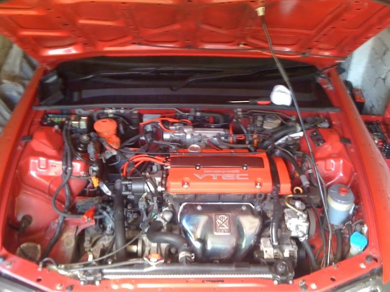
That’s it for this visit, fruits of my labour:
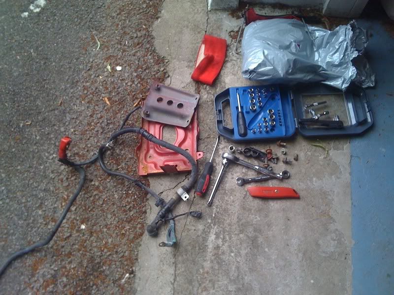
Now sleep my precious…
Onto the next item...
Power Steering Removal
Well along with everything else stripped from the lude, the power steering removal was also on the cards. It was brought to the front of the queue as Lucas needed to get his hands on a pump asap – so another afternoon was put by, free to enjoy the man cave again! Lucas it should be with you shortly.
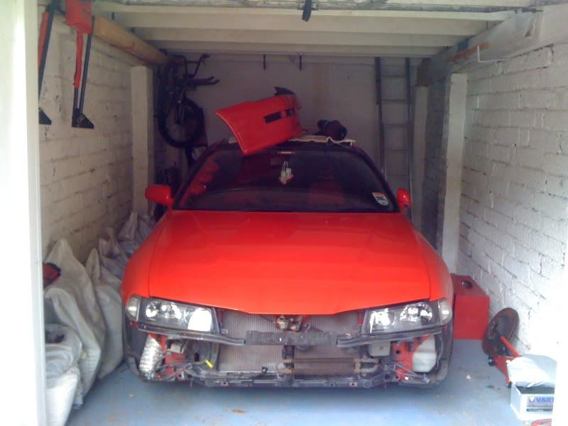
At this point we have a new shed currently awaiting delivery; as a result the garage is a little cramped with loose things around the edge of the car:
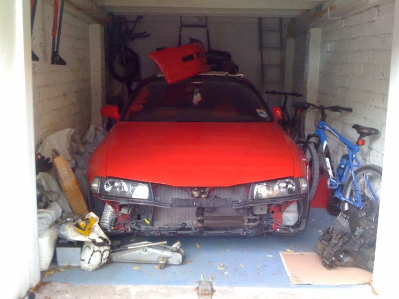
Not ideal, but only temporary. Let’s move some cr@p out the way and crack on…
The usual essay, some pics and a kind of dummies guide coming up!
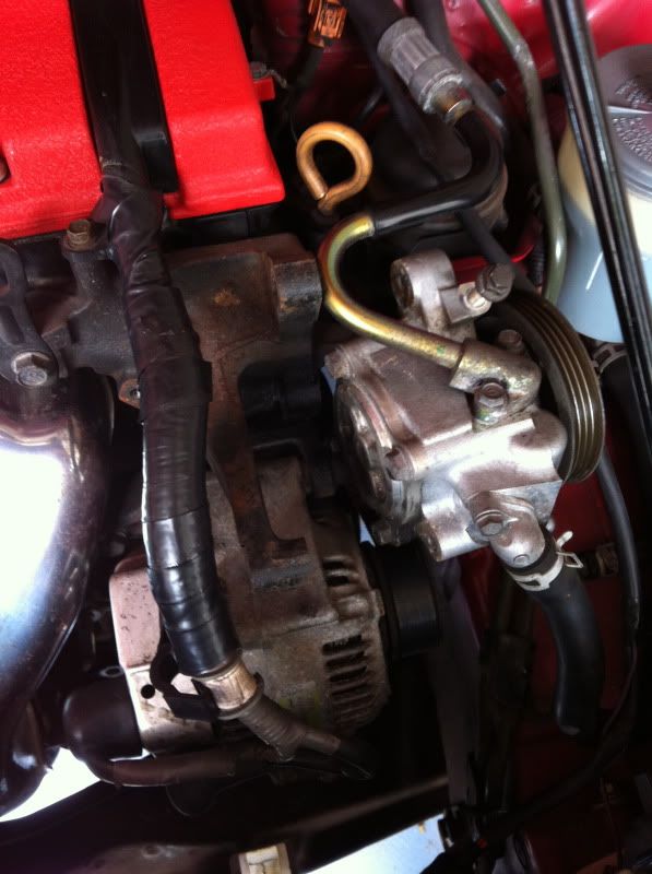
I started off by loosening the pumps tension against the belt. Undo the pinch bolts (x 2) and the pivot point bolt (x 1) - all 14mm from memory??? Then unscrew the tension bolt which pushes against a small cup on the power steering mounting bracket. When loose pop the belt off and put to one side.
I then proceeded to undo all of the bolts fully and remove them all so that the pump hung loose, suspended by the two connecting pipes:
For other people tackling this, I would also slip the reservoir out of its holder – just slides up and out. I had already removed its bracket when removing some A/C lines a while ago so need for me to do this. Again it suspends it self from the three pipes it connects to.
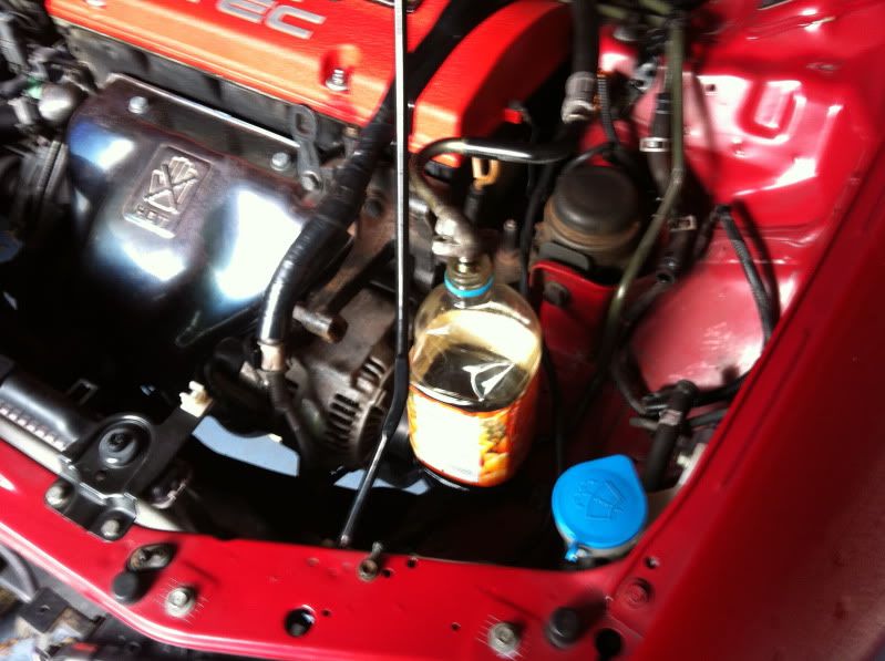
This enables you to manoeuvre the items to drain the most part of the fluid down the pipes, so that I could drain the fluid from as low a point as possible to avoid spilling PAS fluid on any paintwork. The manual suggests for you to drain the fluid from the line near the bottom of the reservoir, but this literally would have been a mess!
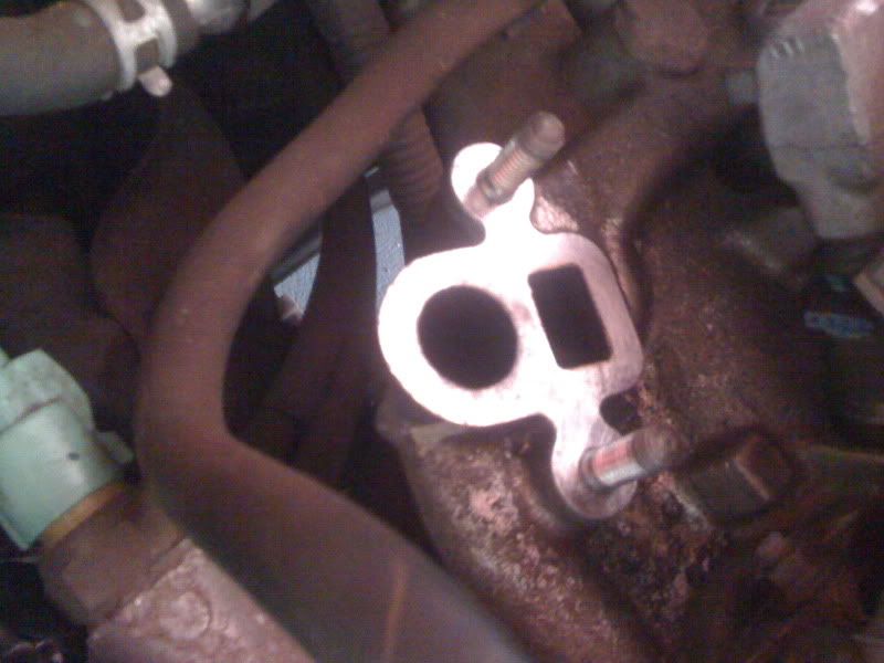
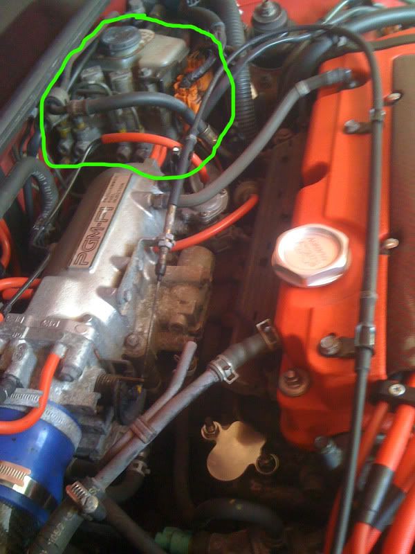
I chose the PAS fluid cooler, being an easy to get to item, very low down and won’t get to any unprotected bodywork metal. For those that don’t know what this item is, when you remove your bumper it sits in front of the radiator on the lower passenger side and looks like a long looped, finned item (like a heating element). I proceeded to remove one of the hoses and drain – mess time!
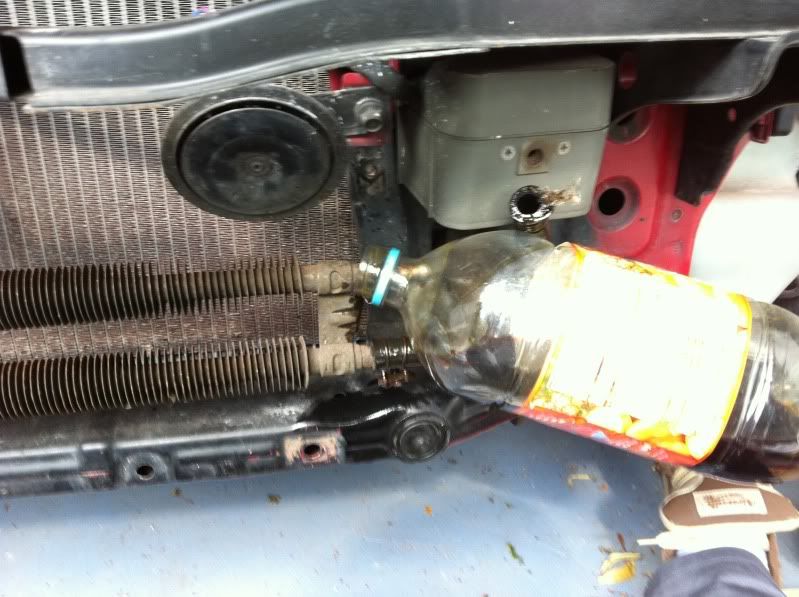
This drains the fluid from the lower pump pipe and the reservoir’s higher of the two bottom hoses. So grab a hold of the pump and reservoir hanging loose and lean them both towards the front of the car to get out as much fluid as possible. I was able to wedge a bottle against things for it to sit on the cooler pipe and catch the odd drip while I removed the coolers mounting brackets.
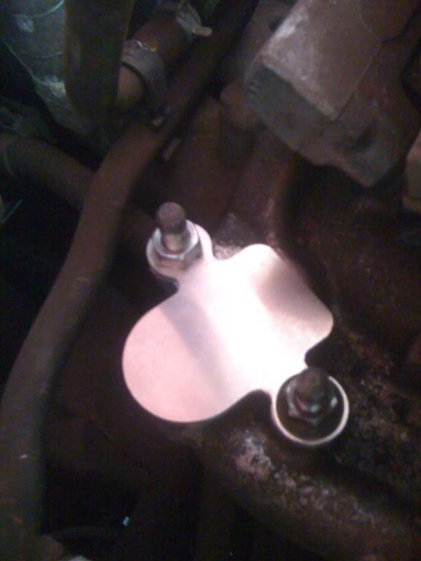
There are two mount points for the cooler, one on the central support – 1 x 10mm bolt, the other to the side where the rubber pipes connect – another 10mm bolt. I removed the other pipe (more fluid to catch!) and then drained the cooler fully.

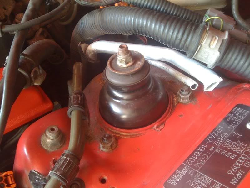
Now back to the reservoir, I removed the top hose facing the front of the car with a rag handy to mop up any excess and wedge some cloth in to block the end. Also throw a load of rags on the engine bay bodywork below just in case.
Then with a little tilting off the reservoir I decided that the tube that comes to the back of the reservoir from over the strut tower was empty to a point. I removed that pipe from the reservoir. I then removed the very bottom pipe from the reservoir but with a rag handy as the draining doesn’t get rid of all the fluid in the reservoir. The reservoir is now free to remove:
Now back to the pump.
Firstly I removed the lower pipe that faces the front of the car – another rag handy as the pump will still want to release more fluid. (I’d already done this in the above pic)
Then remove the top pressurised hard line from the pump, again catch any excess – there will be a bit due to the angle it comes over the rocker/strut area to the pump. I wrapped and tied a rag around the end to stop excess drips.
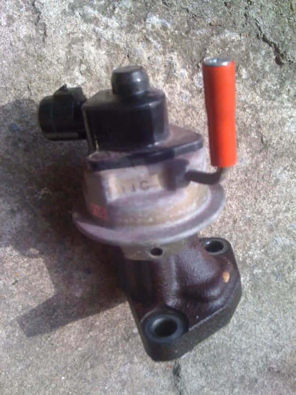
Now whip the pump away – it will still have lots of fluid in. Manoeuvre it every way possible and catch the fluid from either hole. Then again, and then again! Mine wouldn’t stop!
Now onto the pumps mounting bracket. Another 3 x deep bolts require removal – again 14mm from memory??? One of which also doubles up with a looped piece of metal for a chain to connect to for engine removals with a hoist. I’ll keep a deep bolt and the loop in my tool box for removals in the future.
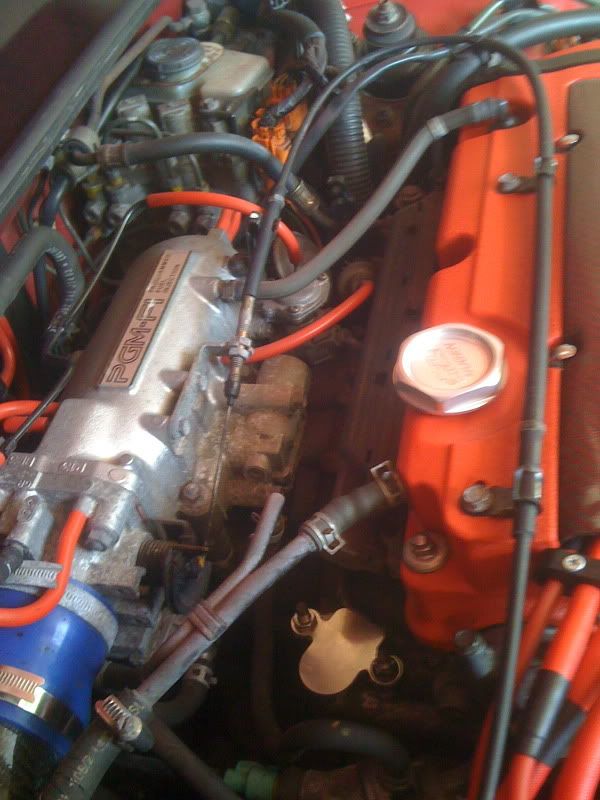
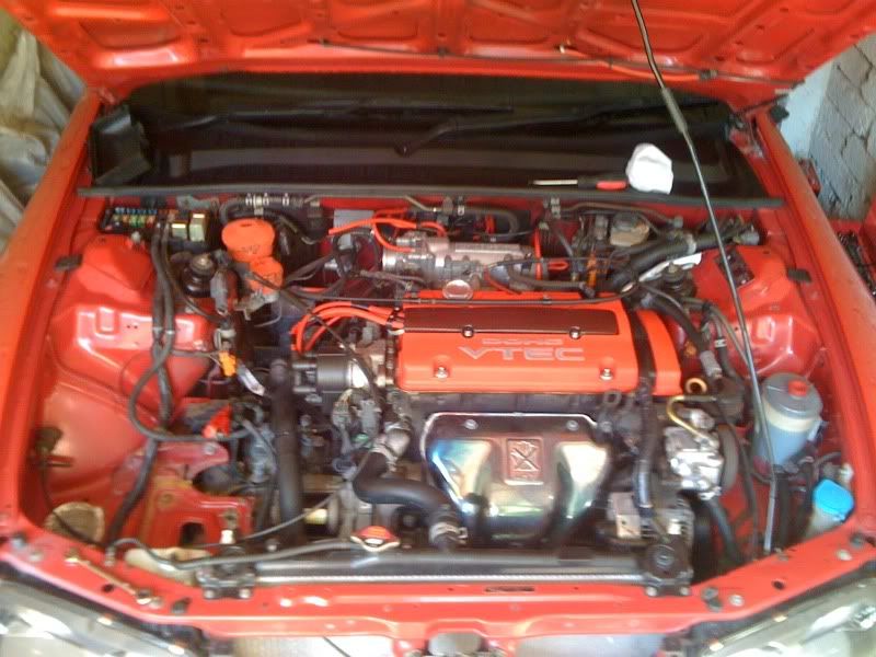
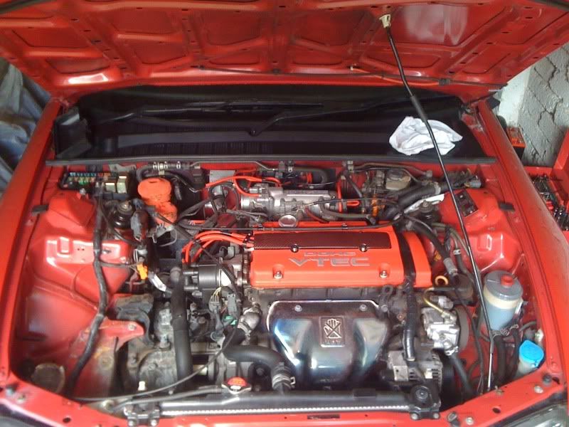
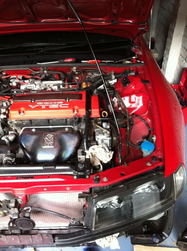
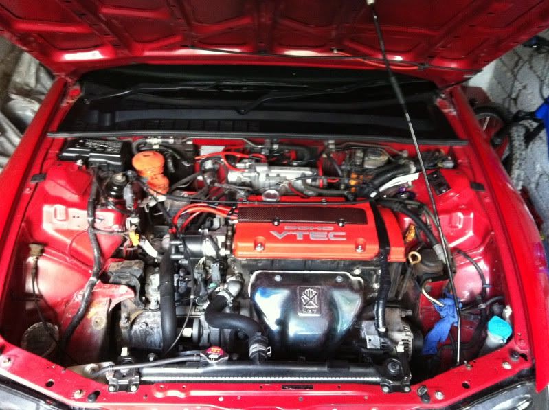
How the engine bay looks now with the main parts removed, except for some of the lines:
From here there is three pipes that go from items removed at the front of the engine bay, up and over the strut tower / rocker cover, and then down the side of the strut tower / back of engine. For me with ABS, this area is annoyingly cramped full of things. Two of the smaller hard line pipes are also mounted to the strut tower with a 10mm bolt!

I then went under the car to where these three pipes come down just above the front main sub frame. The two hard line items bolted to the strut tower connect to some rubber hoses at this point with clips. Remove the clips one at a time carefully with rags and catch the fluid in a bottle. Very difficult not to make a mess as the n/s inner CV boot is right below – try to avoid covering it with fluid!
This is as far as I got for the day as I moved onto something else on the car, which I’ll cover in my Profile for other none engine build related items, there is a clue on the engine bay pics below on one side.
There is less and less in the engine bay now, getting there slowly. Makes me realise just how much cr@p I had in there! All no good to me now:
Next update will show me removing the remaining pipes up to the steering rack and VSS and looping the lines on these. However the 10mm bolt next to the ABS may have to wait until the ABS is fully out of the way! I’ll just break / cut the lines at this point.
Then I’m moving onto the charcoal canister and associated evap stuff. Then finish removing the intake manifold to get cracking with the ABS removal – more fluid mess!
A couple more days work I think and I’ll be onto the ABS removal as I know a few of you have been waiting for it.
Cheers,
Rob