

You can shim the whole mechanism from underneath, which will bring it down some. I actually redid mine last week and its now bob on.
Though looking at the pics, that's not a full 5th gen conversion? The new mechanism appears to be a 4th gen one with a glass roof? Do you have the sliding shade?
Congratulations to vtecmec for winning May/June's Lude Of The Month, with his DIY Turbo BB1 build.
>>> Click Here For Profile <<<

>>> Click Here For Profile <<<
Sol-Lude's Build
-
sol-lude

- Posts: 1032
- Joined: Wed Jul 17, 2013 1:48 pm
- My Generation: 4G
- PSN GamerTag: Lude_666
- Location: Kirriemuir
- Has thanked: 10 times
- Been thanked: 18 times
Re: 2nd lude build: update lots of rust and new parts
That was my thoughts also as there was no cover over the motor like in your build I purchased it like this. I don't have the sliding shade but I will need to hunt one down. I don't have an internal picture but you can see a few nuts on the inside still.Vtecmec wrote:You can shim the whole mechanism from underneath, which will bring it down some. I actually redid mine last week and its now bob on.
Though looking at the pics, that's not a full 5th gen conversion? The new mechanism appears to be a 4th gen one with a glass roof? Do you have the sliding shade?
-
sol-lude
- Posts: 1032
- Joined: Wed Jul 17, 2013 1:48 pm
- My Generation: 4G
- PSN GamerTag: Lude_666
- Location: Kirriemuir
- Has thanked: 10 times
- Been thanked: 18 times
Re: 2nd lude build: update lots of rust and new parts
Thanks man very helpful I'll get the link sorted tomorrow.Drax wrote:brilliant work here sol-lude fair play
to link your build into your signature, just go to the first page of your build then copy the url from the top of the web page, then go to My Profile at the top of LG page, then choose My Control Panel, then select the Profile tab and choose Edit Signature.
Paste the url here, then highlight it all and click the URL option above the writing. then click SUMBIT at the bottom. sorted.
sunroof swap wise, maybe this guide can help?
http://www.ludegeneration.co.uk/honda-p ... t4533.html
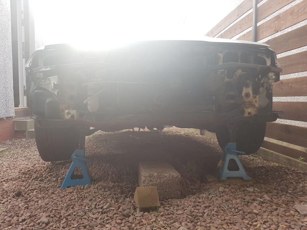
Yeah I have replacement arches and @vtecmec's build has more than inspired me to know I can do all of this myself...well most of it.wurlycorner wrote:Well done for tackling this.
That is quite a bit of rust on those rear quarters, yep. All repairable though yes - just needs quite a bit of work.
Those connectors would be for fogs, as others have said. Looks like they have been hacked about a bit though.
The 5g sunroof does sit a bit high in a 4g, but there are several here that have done it and some have adjusted it down a bit. Can't remember all the owners that have fitted it, but @Vtecmec is one of them...
Some of the underbonnet stickers are still listed as available new from honda
So I might be able to get these from Honda you say I'll have to get in touch with them. Thanks again
-
sol-lude
- Posts: 1032
- Joined: Wed Jul 17, 2013 1:48 pm
- My Generation: 4G
- PSN GamerTag: Lude_666
- Location: Kirriemuir
- Has thanked: 10 times
- Been thanked: 18 times
Re: 2nd lude build: update lots of rust and new parts
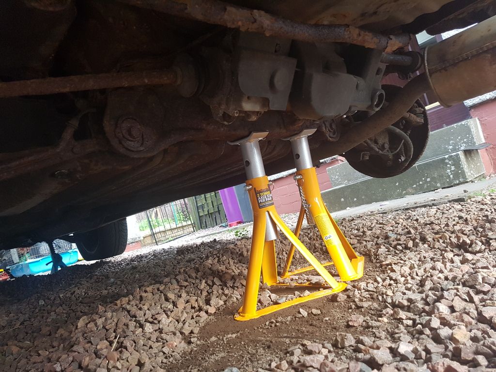
Not much of an update got the car up on axle stands had someone question the security of it tried a good old wobble and jump no movement.
I'm hoping to get the EL dials sorted before taking out the engine so just need to get finger out and sort the wiring.
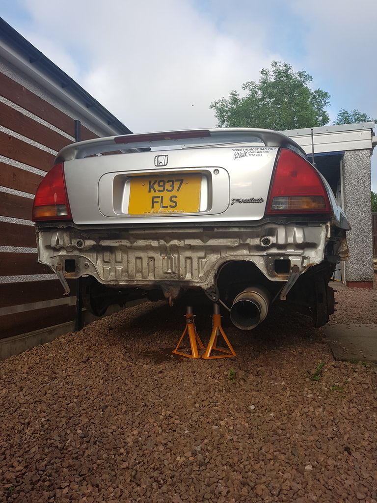
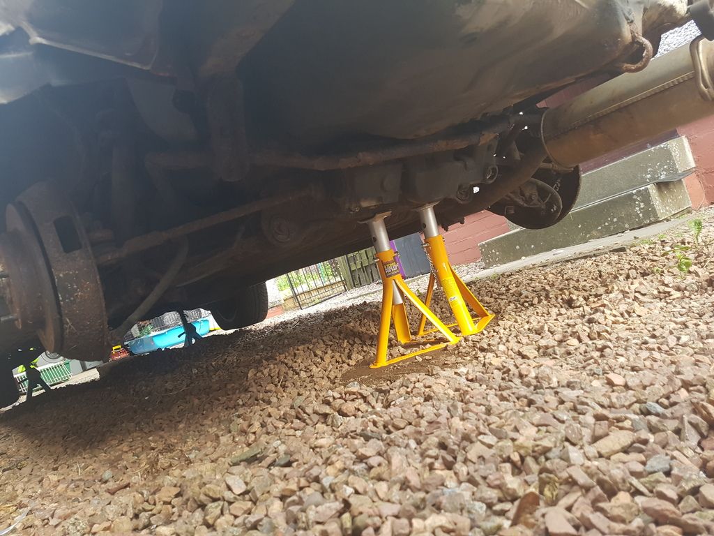
Halfords have these stands on special at a 10r the now
I'm hoping to get the EL dials sorted before taking out the engine so just need to get finger out and sort the wiring.


Halfords have these stands on special at a 10r the now


Last edited by sol-lude on Fri Aug 04, 2017 8:39 am, edited 1 time in total.


-
sol-lude
- Posts: 1032
- Joined: Wed Jul 17, 2013 1:48 pm
- My Generation: 4G
- PSN GamerTag: Lude_666
- Location: Kirriemuir
- Has thanked: 10 times
- Been thanked: 18 times
-
sol-lude
- Posts: 1032
- Joined: Wed Jul 17, 2013 1:48 pm
- My Generation: 4G
- PSN GamerTag: Lude_666
- Location: Kirriemuir
- Has thanked: 10 times
- Been thanked: 18 times
Re: 2nd lude build: update lots of rust and new parts
So finally an update on the EL dials all done and dusted. I will be putting a how to together for this it seems there are how too's here there and everywhere. Amalgamated with the help of everyone on here and a special mention to bennyboy who helped and also sourced the missing piece of my jigsaw.
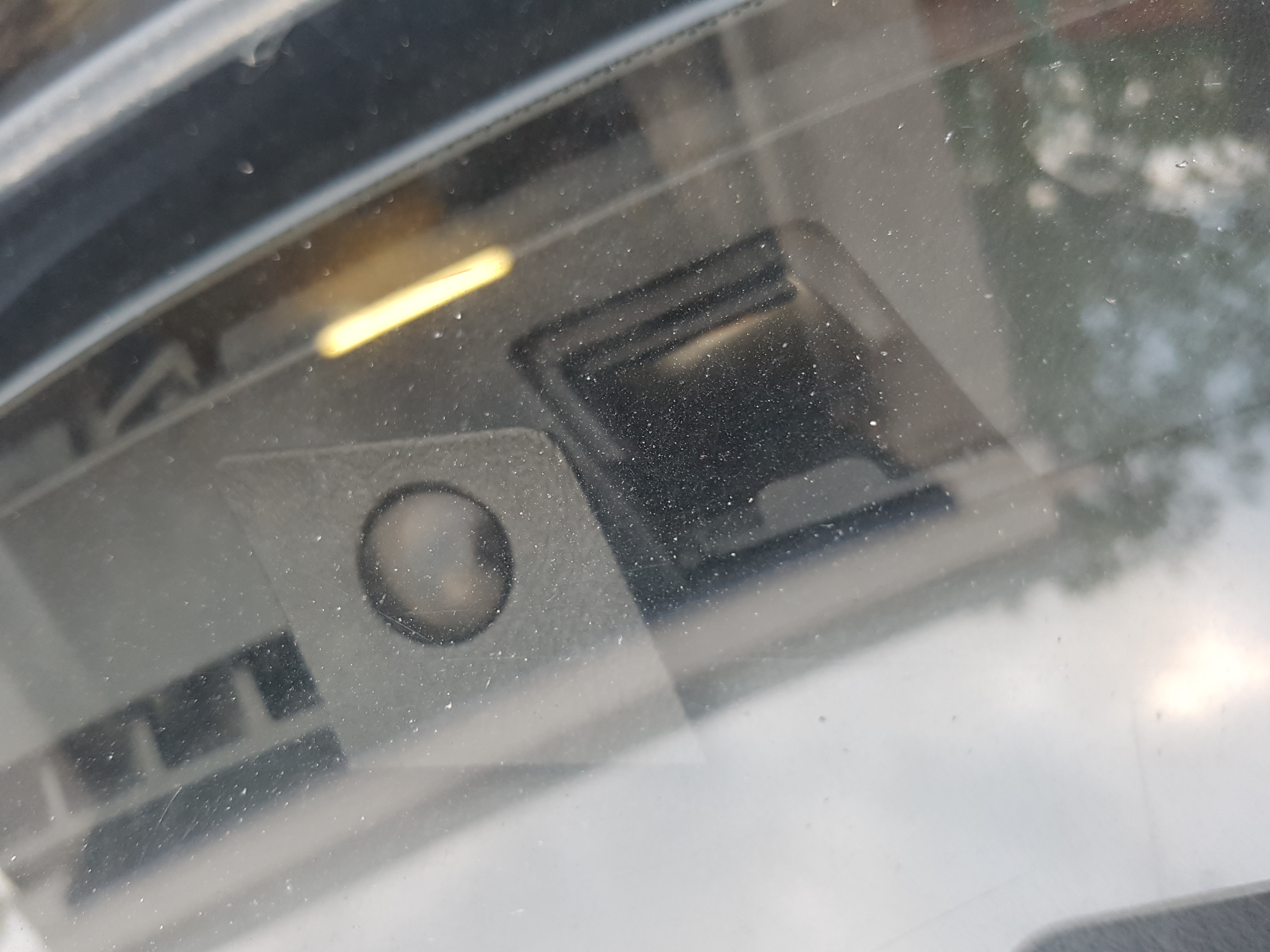
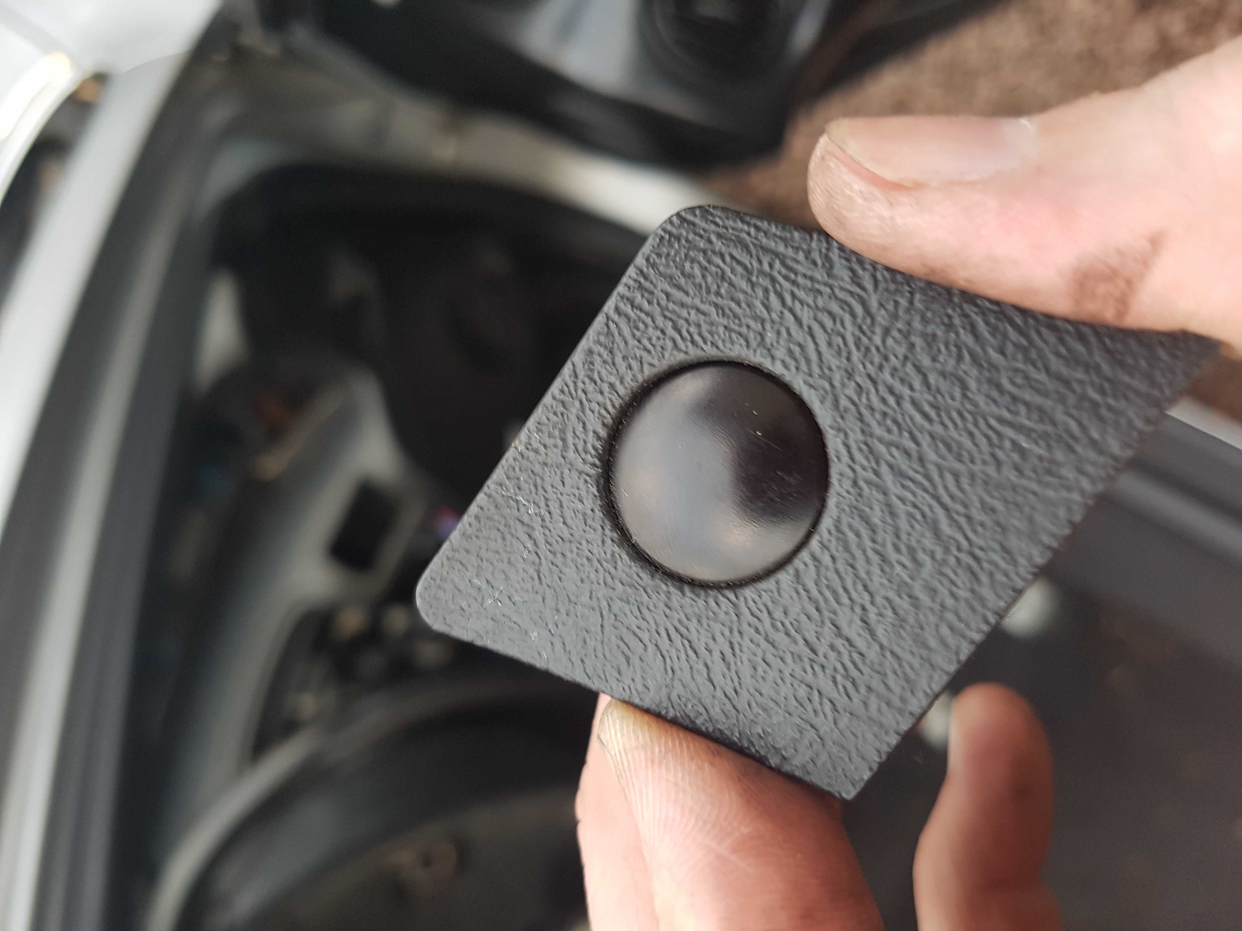
Also popped in the face lift tweeter covers.
How to to follow when I get some time.


Sent from my SM-G935F using Tapatalk
Also popped in the face lift tweeter covers.
How to to follow when I get some time.
Sent from my SM-G935F using Tapatalk

-
sol-lude
- Posts: 1032
- Joined: Wed Jul 17, 2013 1:48 pm
- My Generation: 4G
- PSN GamerTag: Lude_666
- Location: Kirriemuir
- Has thanked: 10 times
- Been thanked: 18 times
Re: 2nd lude build: update lots of rust and new parts
Cheers mate, it is much appreciated. So much easier when you have all the pieces of the puzzlebennyboy wrote:No problem at all @sol-lude, glad we got there in the end and the part has been put to good use.
Enjoy the EL's they are a real part of 4th gen history/character IMHO.
I think they look great.
Just a pitty I cant get her on the road the now - its an itch that's going to take a while to scratch haha.
-
sol-lude
- Posts: 1032
- Joined: Wed Jul 17, 2013 1:48 pm
- My Generation: 4G
- PSN GamerTag: Lude_666
- Location: Kirriemuir
- Has thanked: 10 times
- Been thanked: 18 times
Re: 2nd lude build: EL Dials intallation with 4WS and TCS
Evening all, i was hoping to have had this done but due to photofuckit ive spend the last hour finding the best hosting site where i could upload multiple (although nothing over 5mb  )
)
Anywho i know some/a few have done this and a few planning to do it...now i probably made more work for myself than needed but im happy in the knowledge it all works.
Now im not going to lie i used ammo post http://www.ludegeneration.co.uk/honda-p ... -t890.html for a lot of my help.
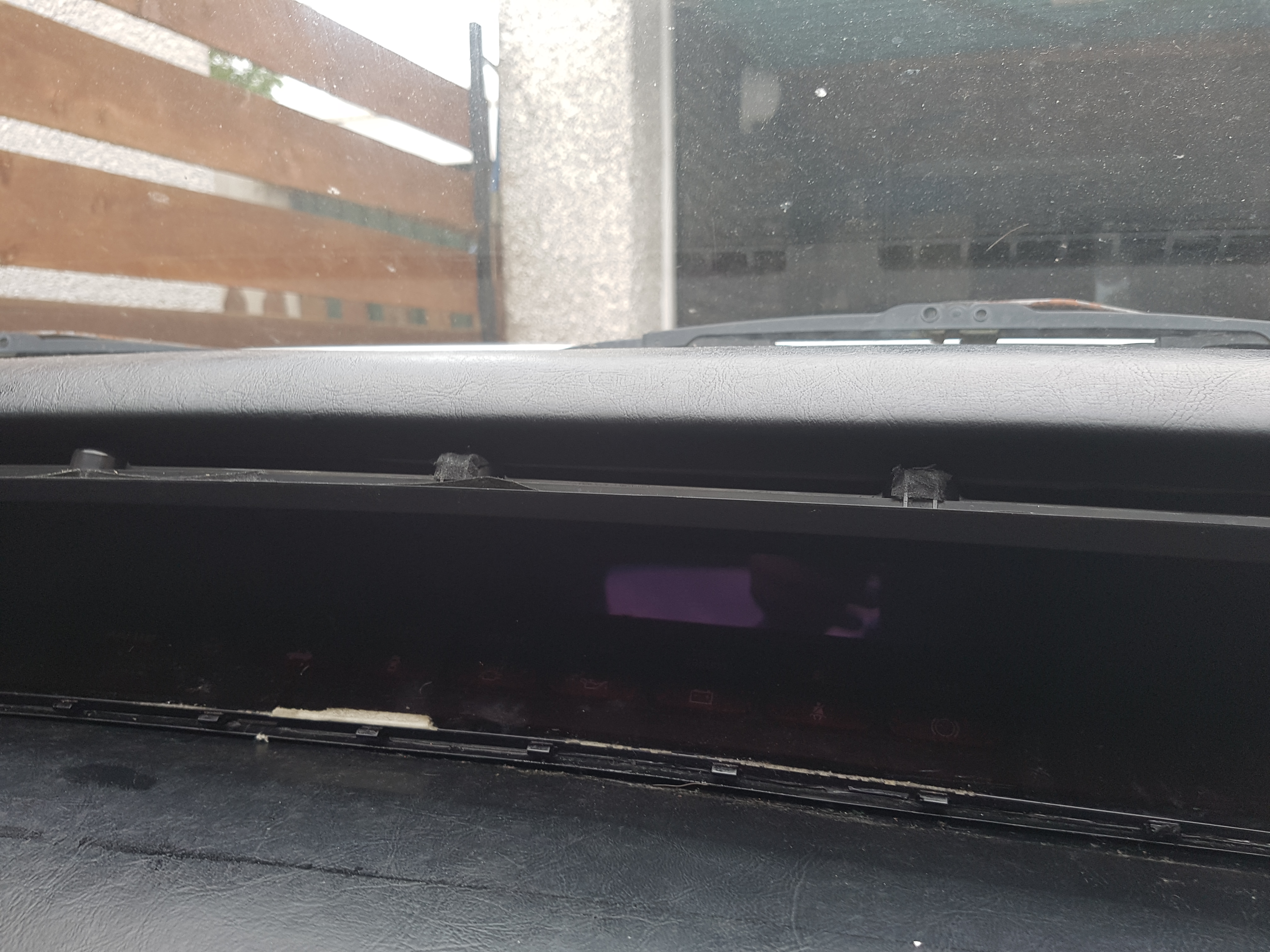
1st remove the tweeter covers (1st image ove 5mb)
pull off rubber seal at the bottom of the dash
then remove the 6 (i think) screws at the top of the dash
remove dash joint cover
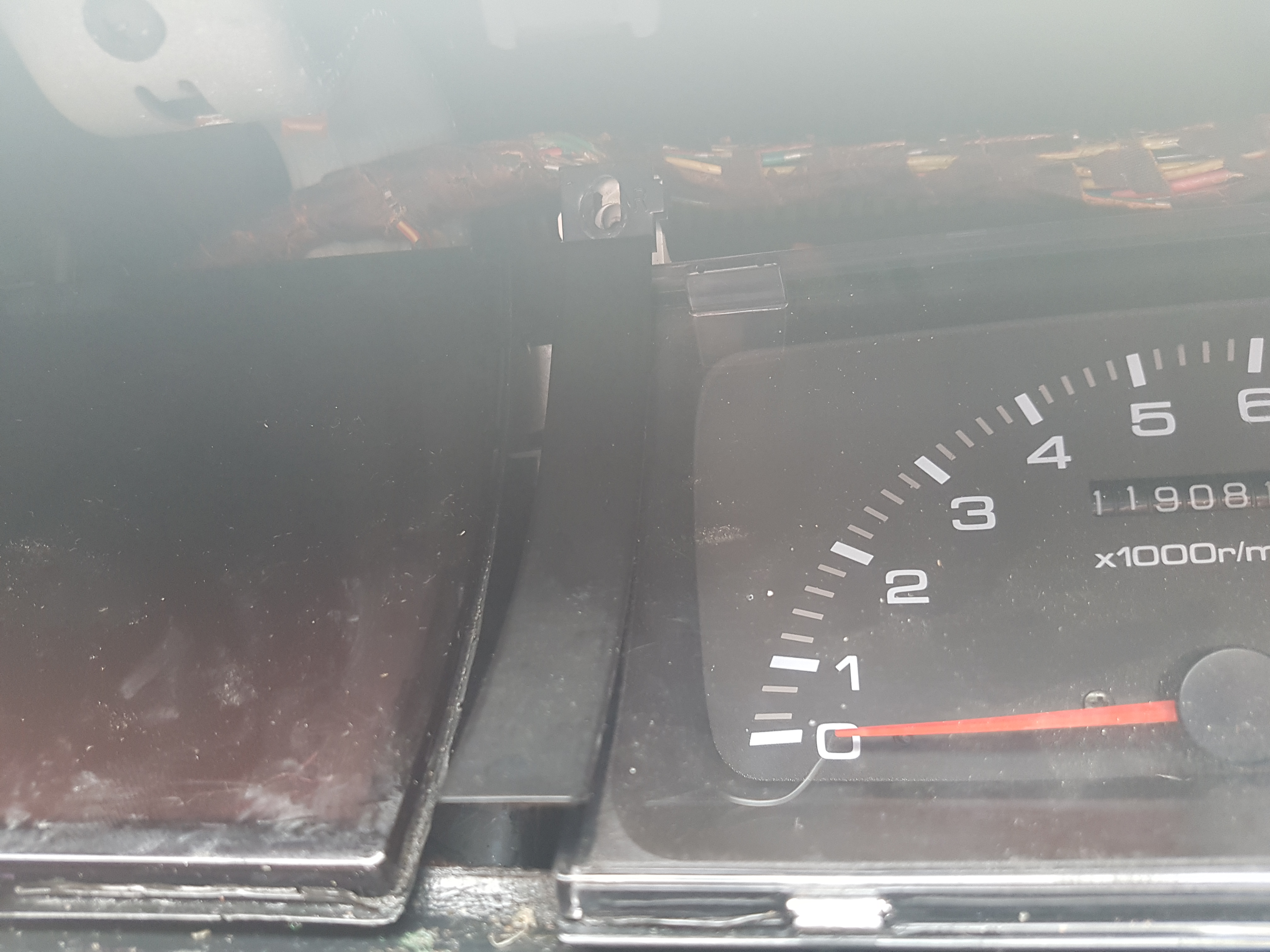
Then remove the screws holding in the dials and the fuel/temp section should be 4 in each. Remove the plugs and set old dials to the side.
You should have it looking like this
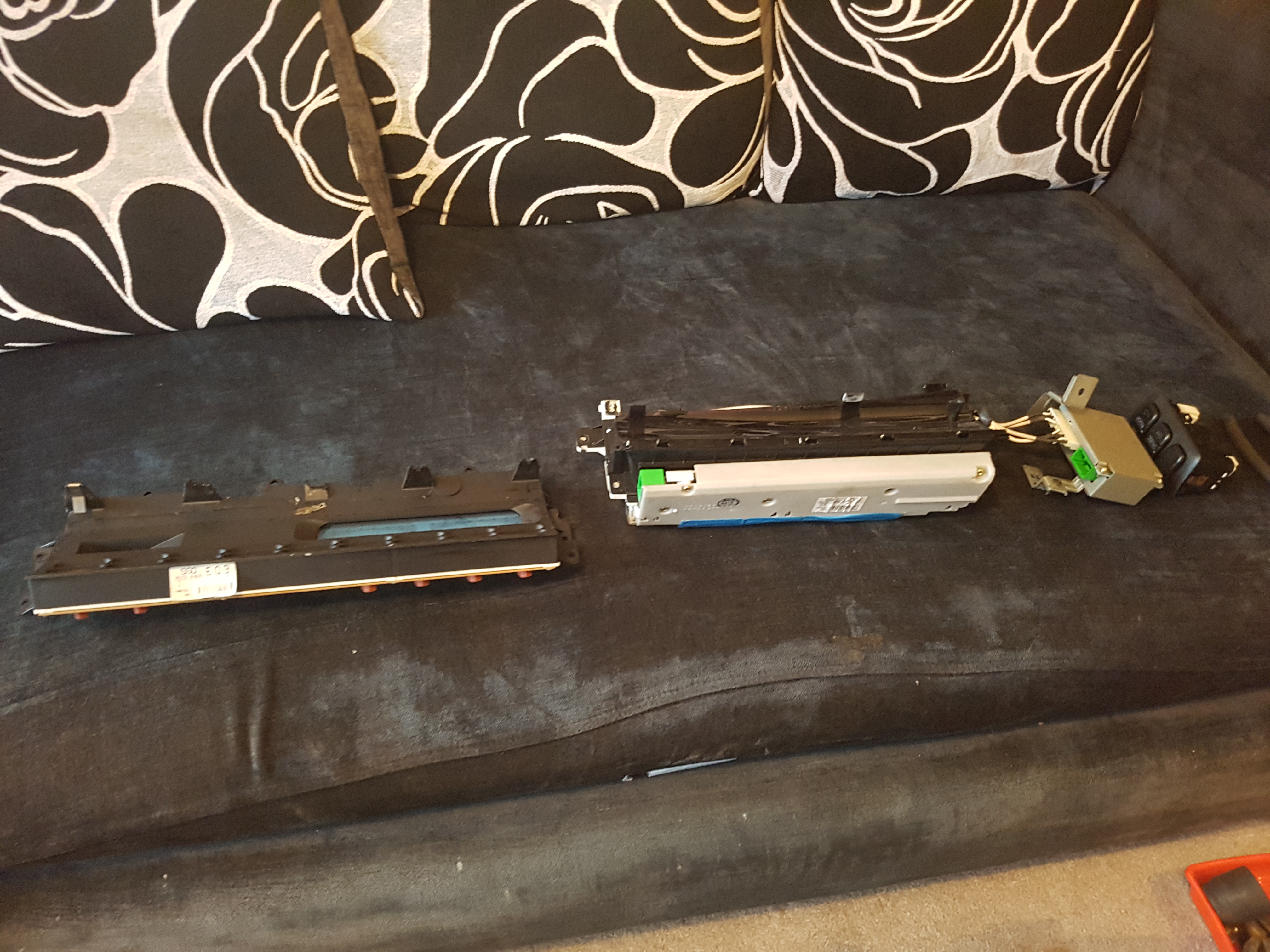
Remove the white box also

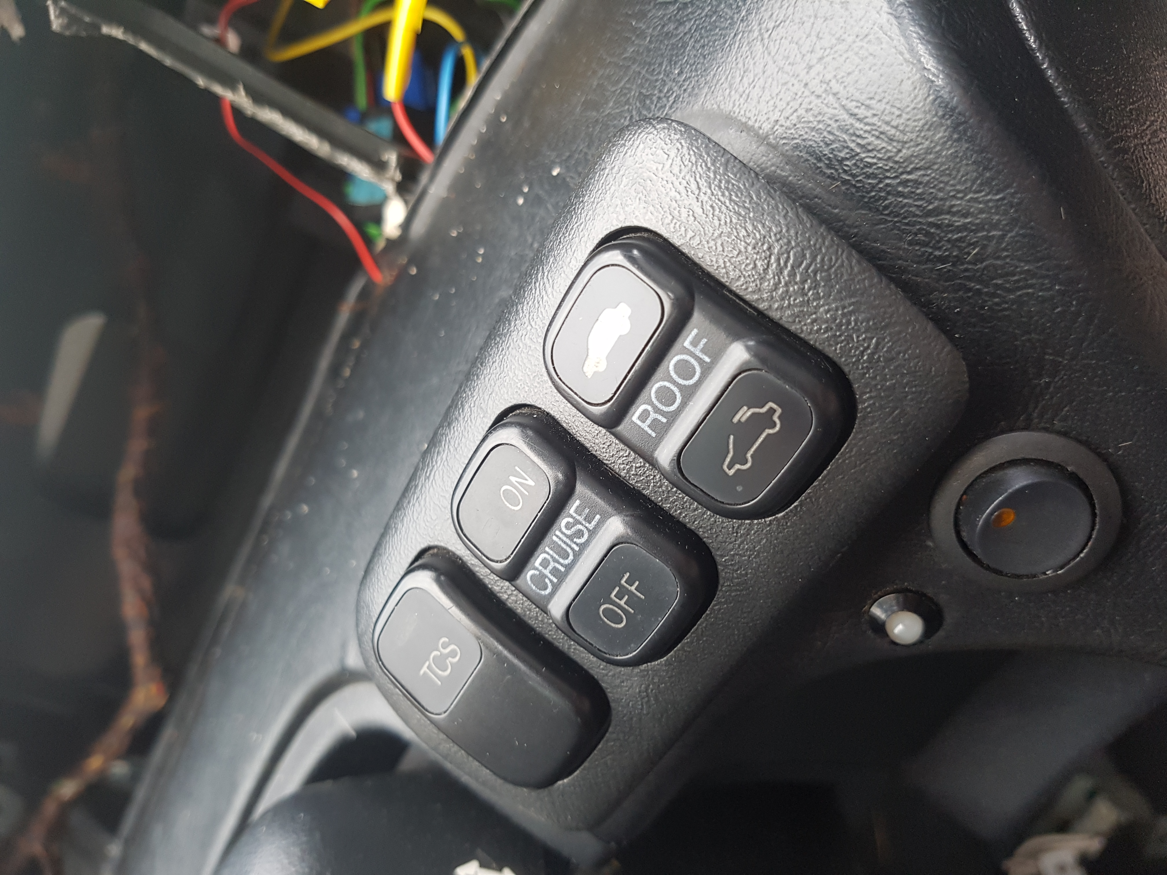
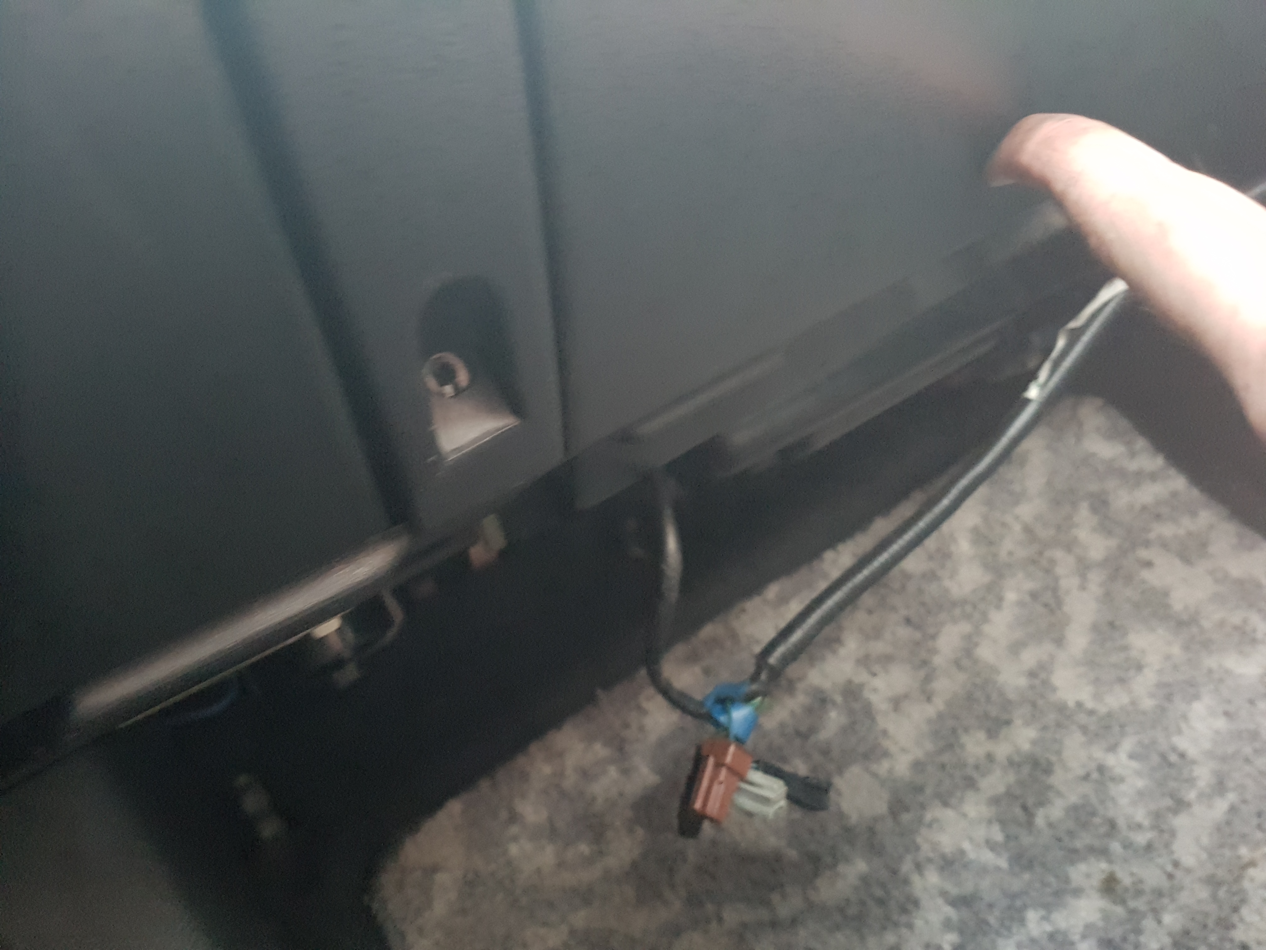
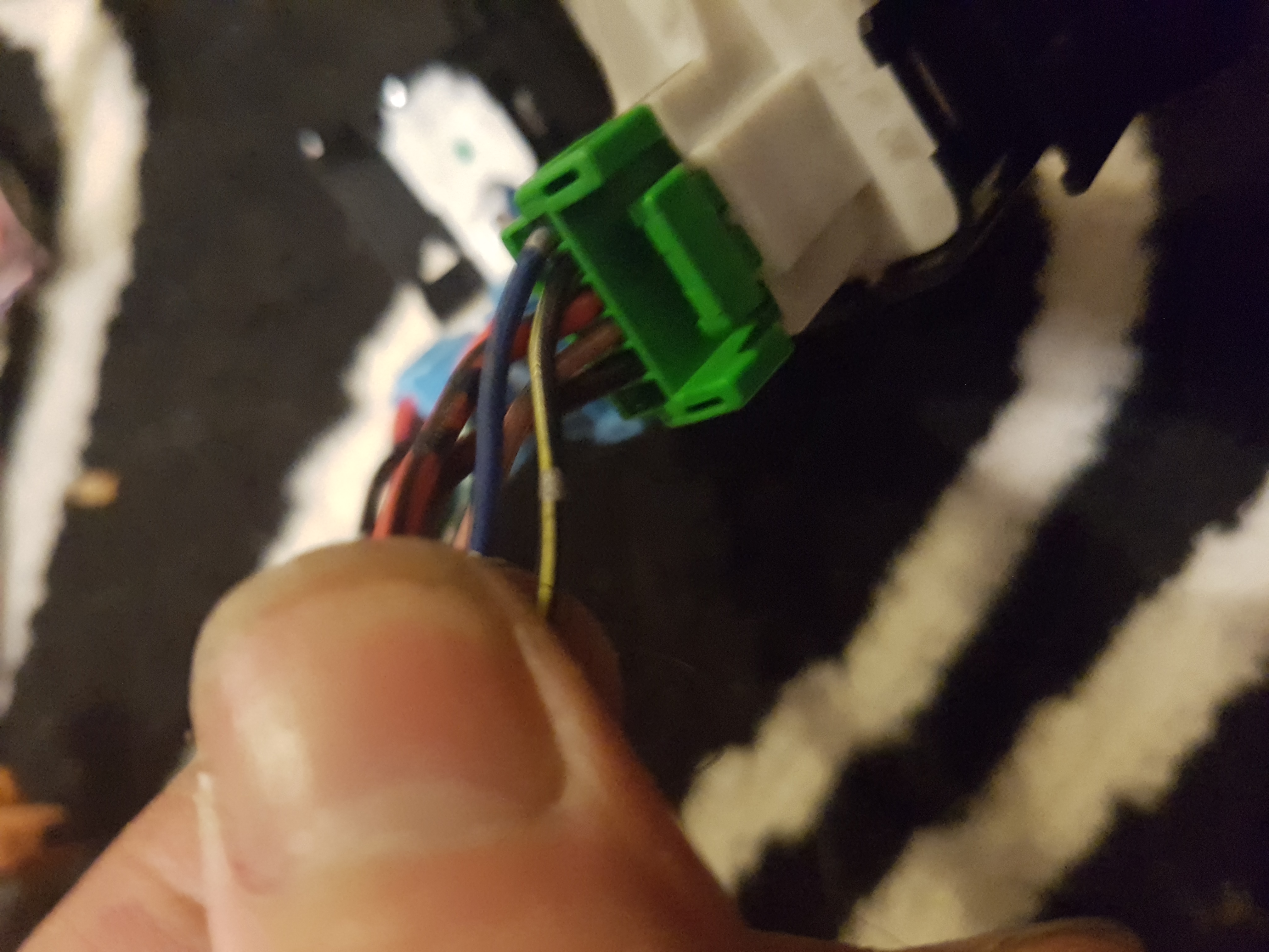
Pull out the switches and remove the plugs
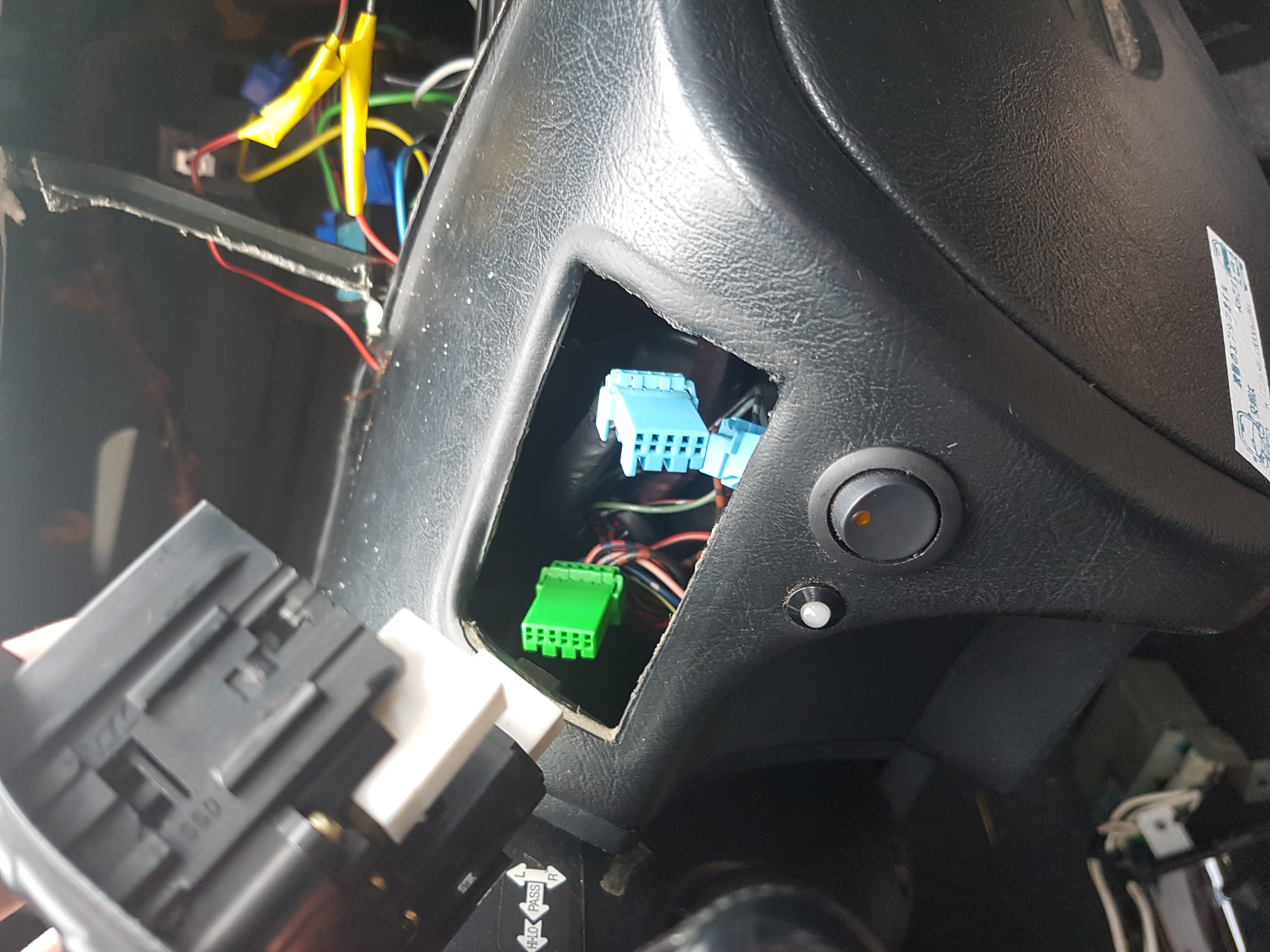
now in the driver footwell there are 3 plugs 2 grey 1 blue. Remove these.
then at the passenger footwell remove the glovebox number of screw in and around the glovebox
Remove the two grey plugs here also
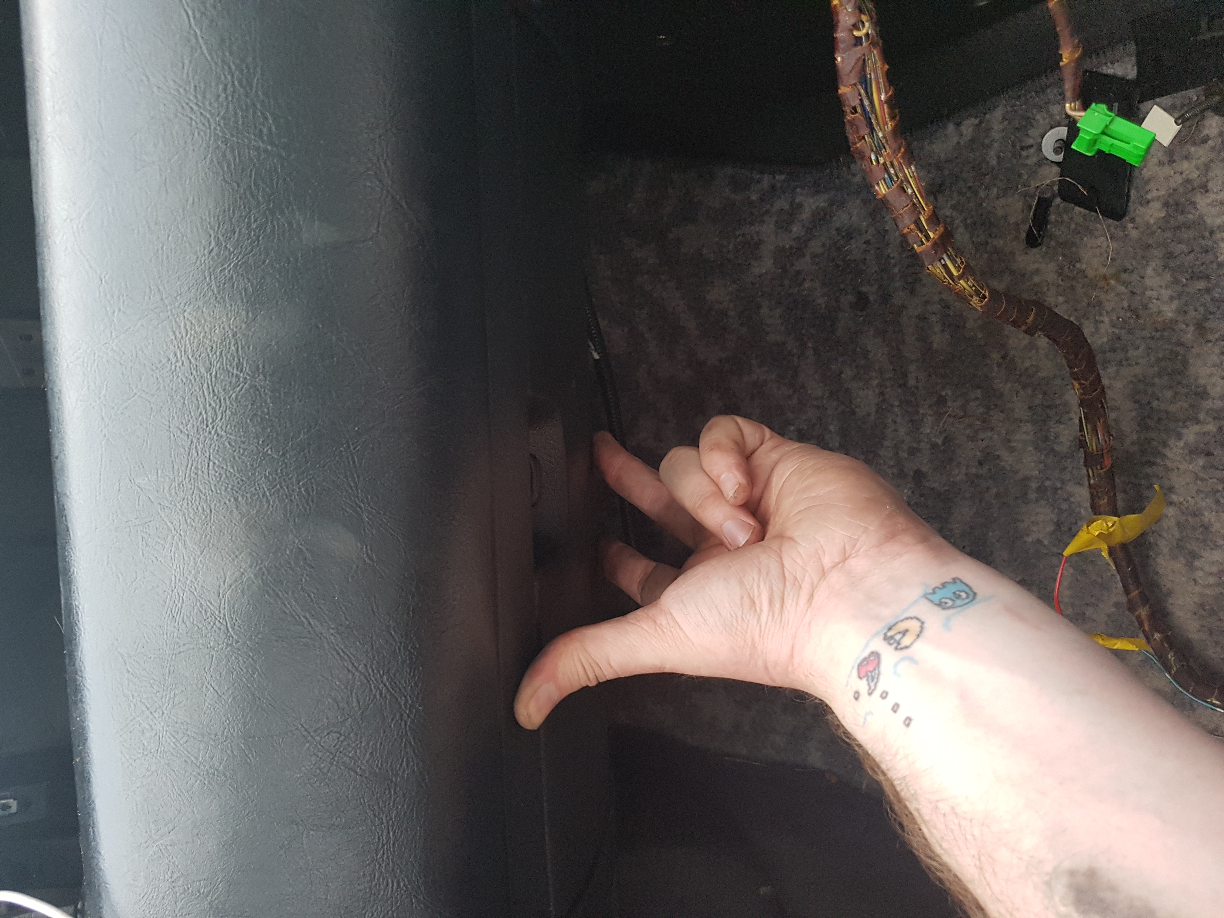
then feed these up through the dash on both sides.
I came across the temp sensor on the dash. this is quite tricky and i removed the dash screws and and then use a screwdriver to pop through (be careful not to damage this) then remove the plug
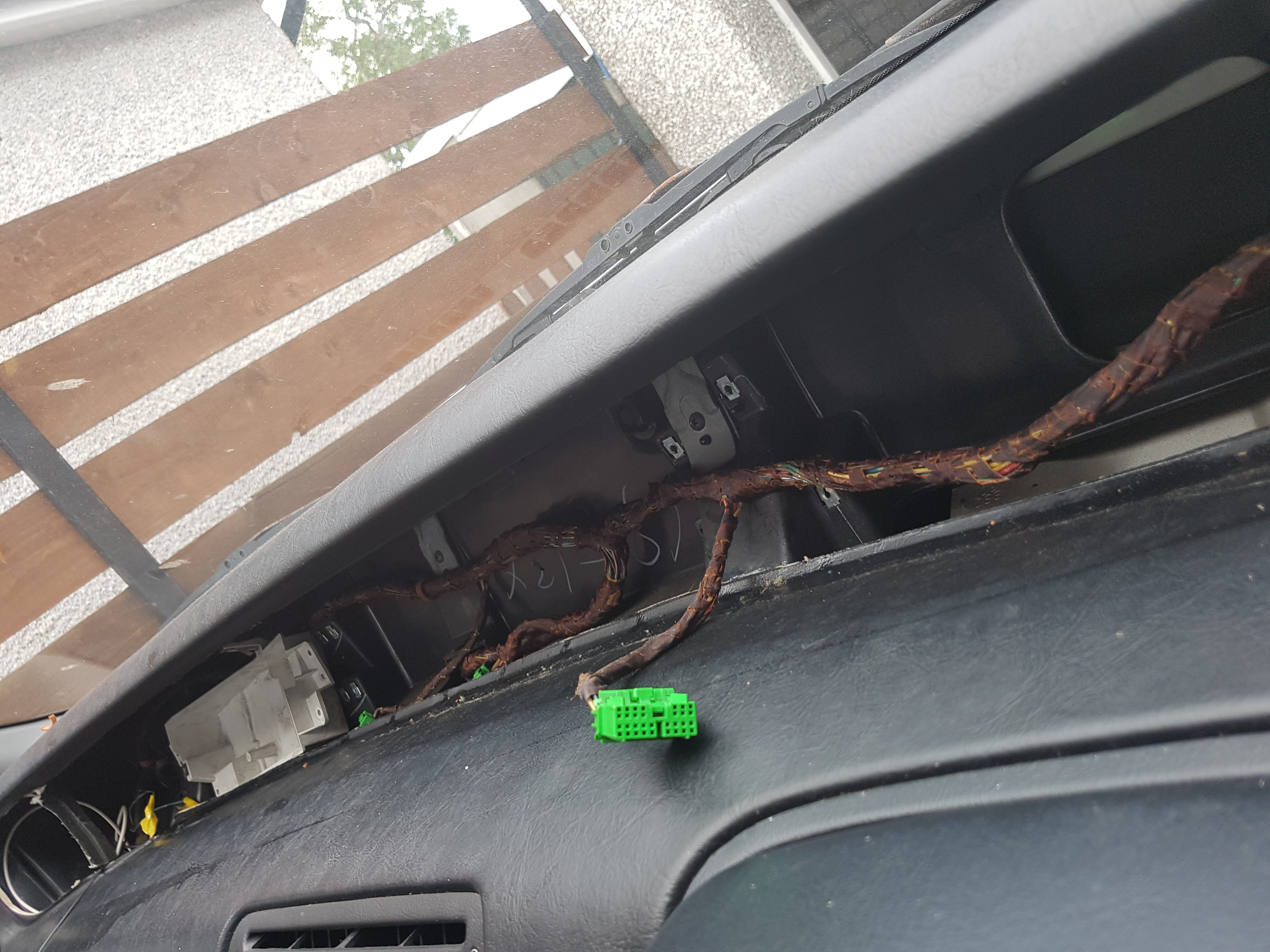
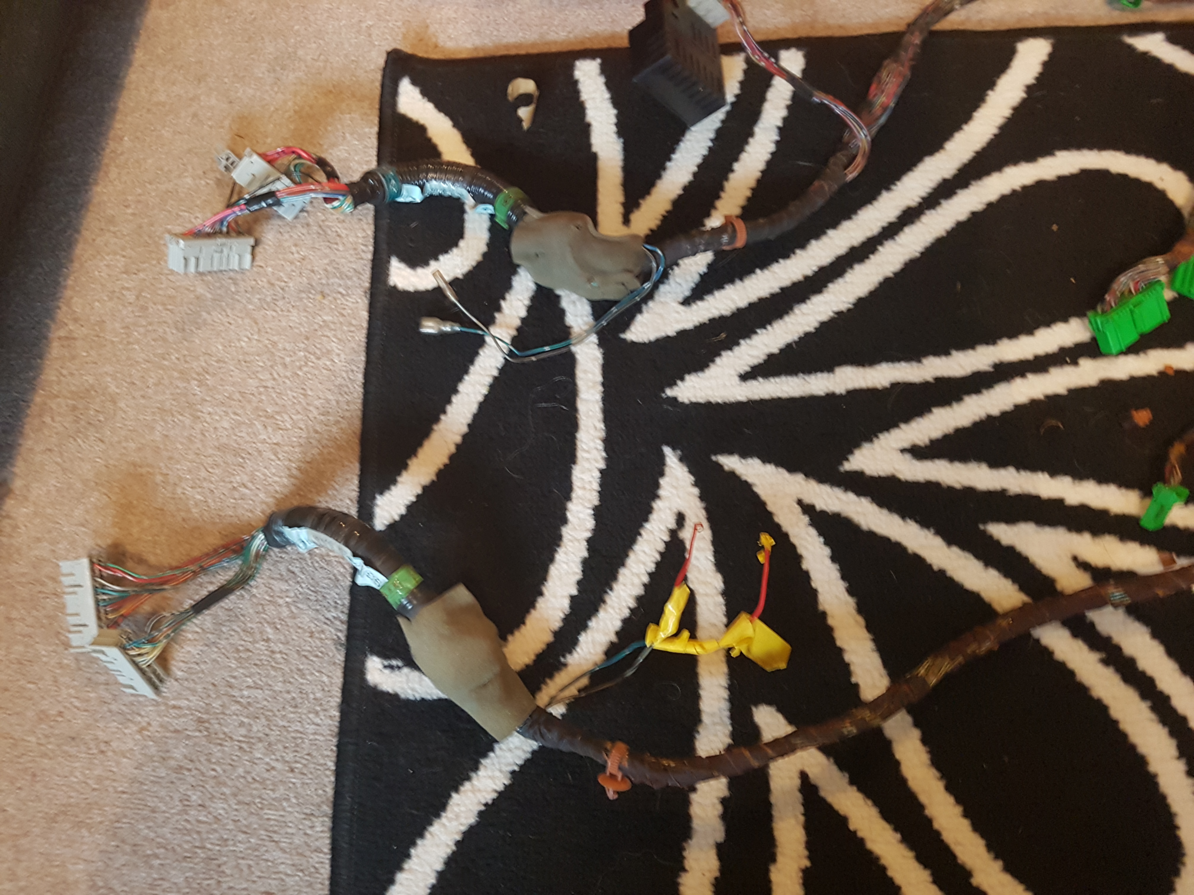
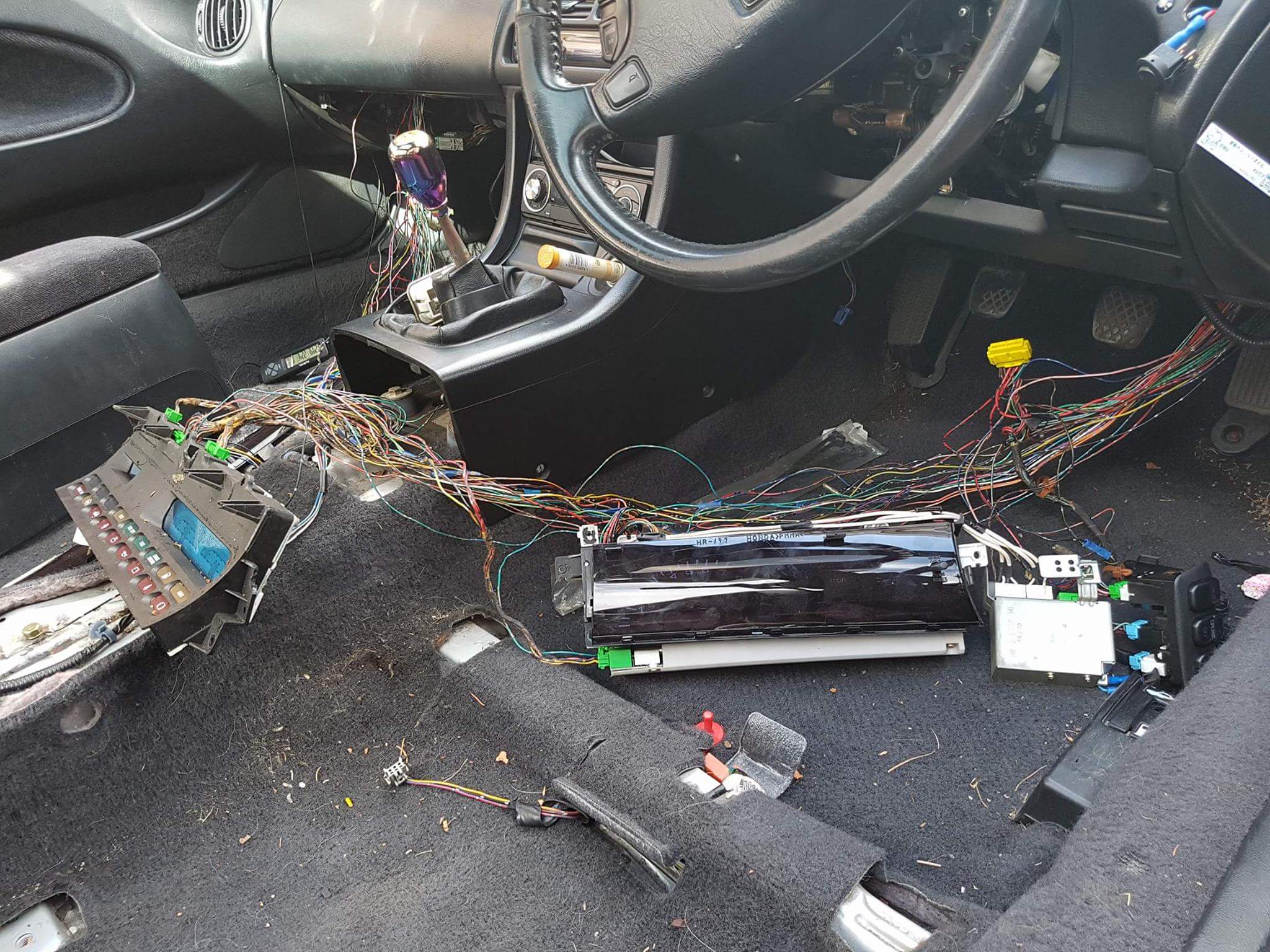
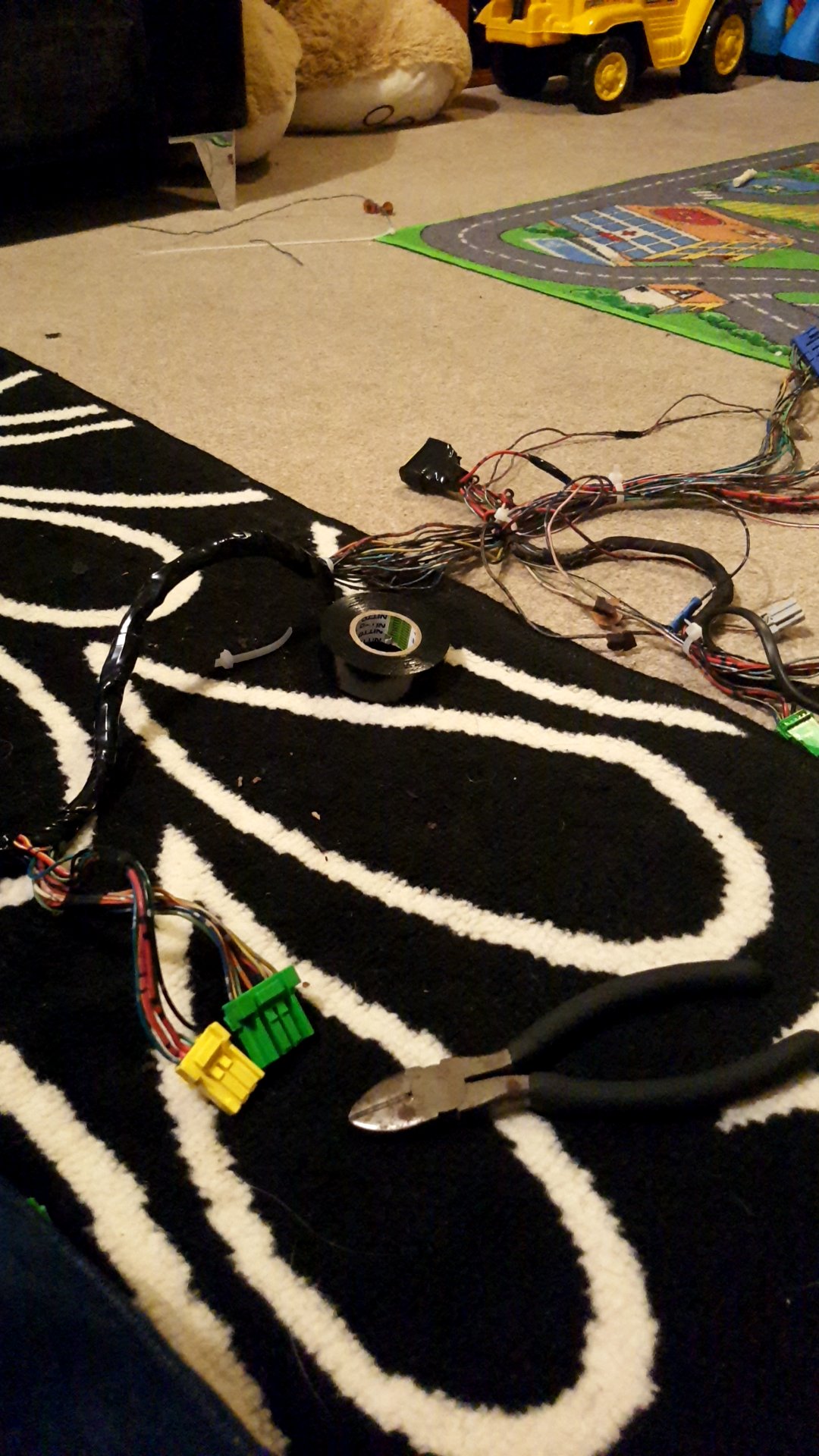
Then it was probably a good thing the other half works nightshifts with the mess i made. As you might find the tape used is stickier than The Dead Marshes by Mordor. Use gloves or have wipes handy.
Both looms
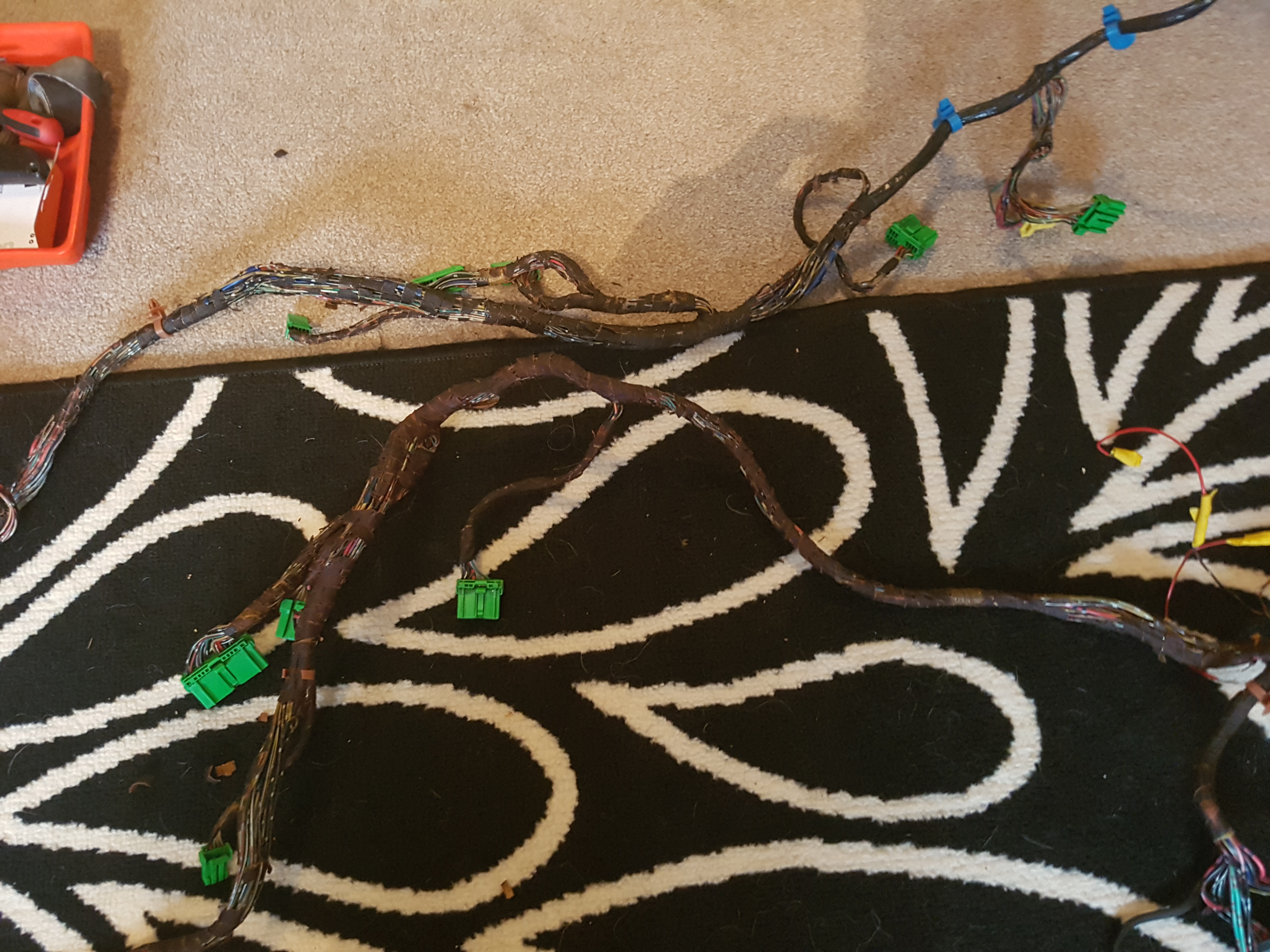
Now the next part is purely a follow the colour and wire exercise. I removed all the loom tape from both however this wouldnt be needed.
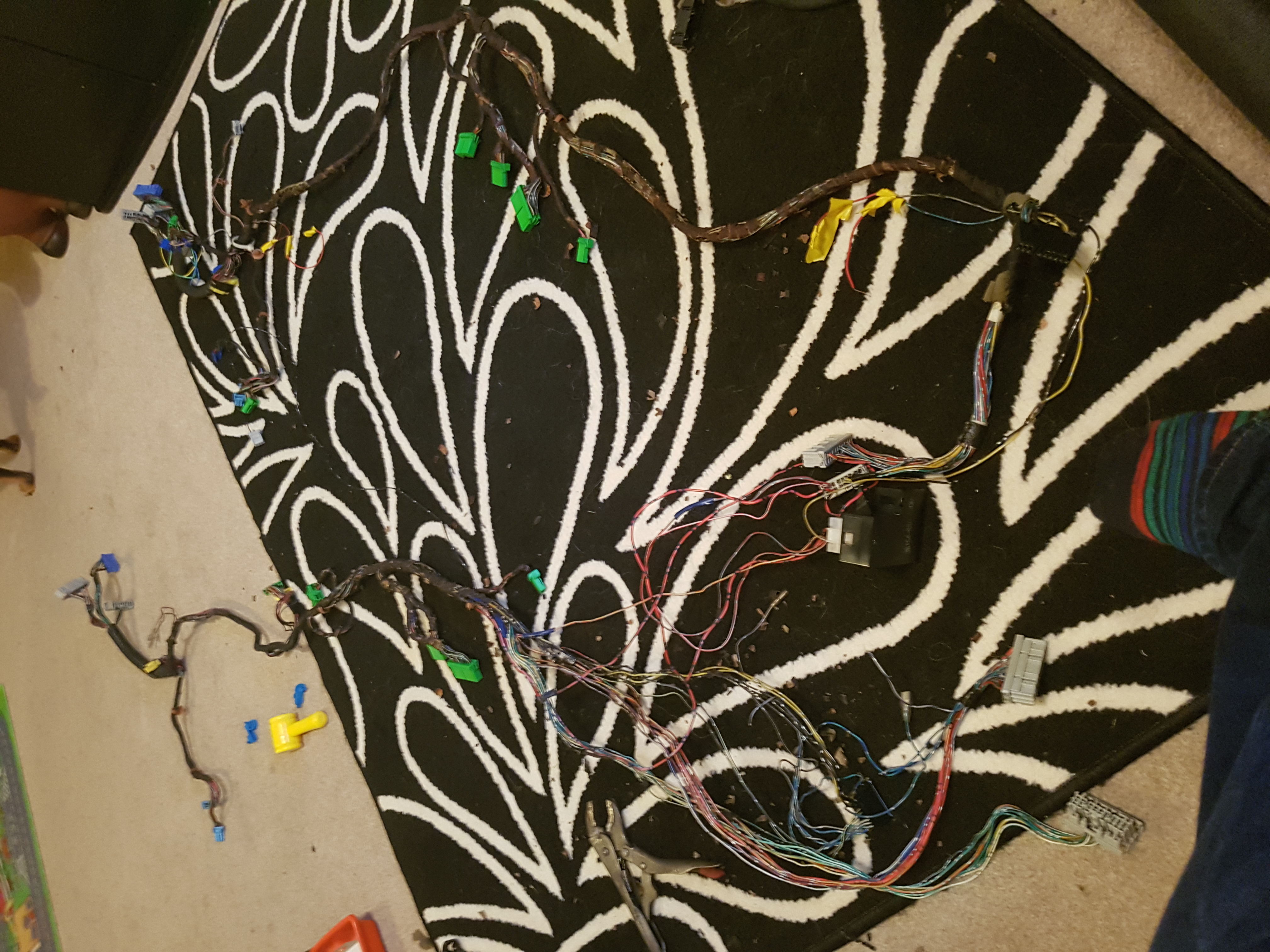
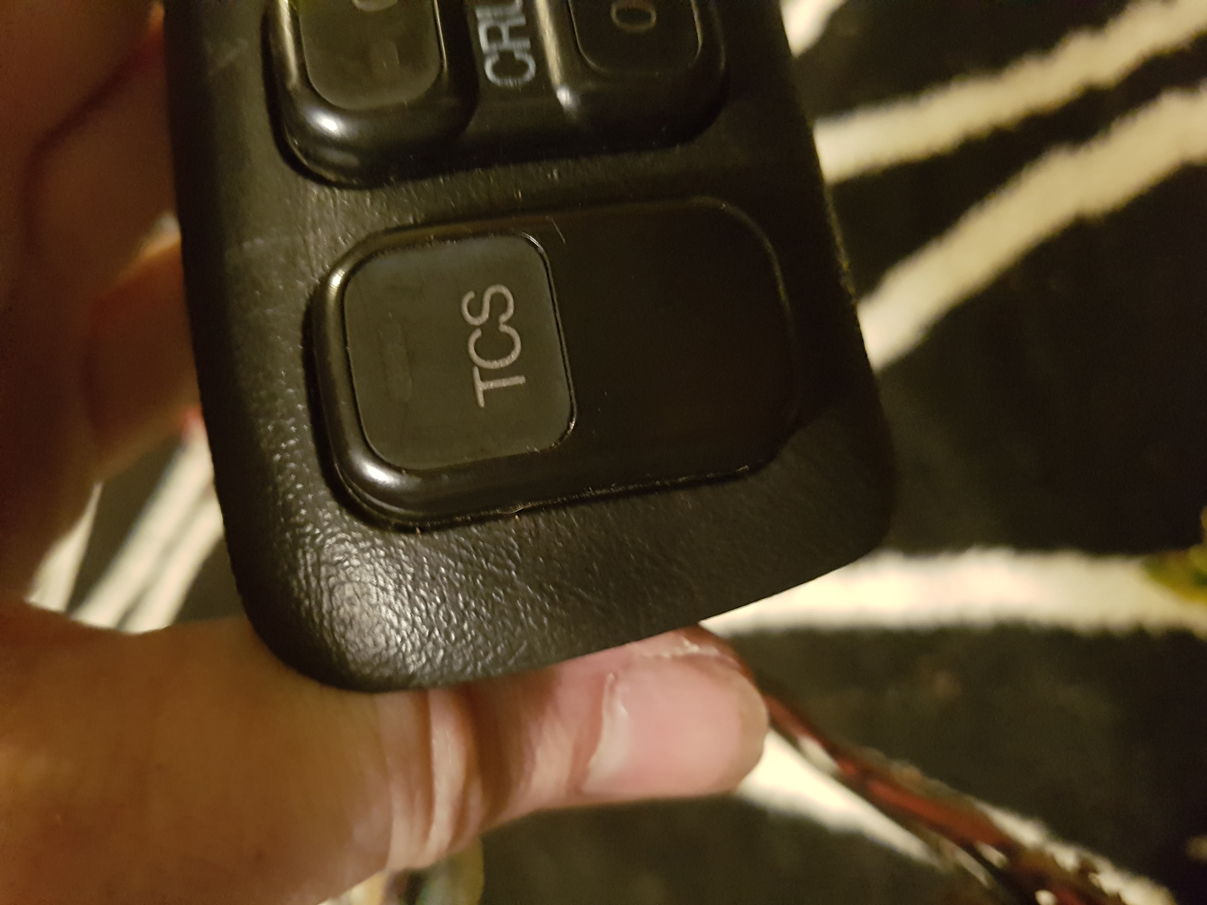
1st i took the plug for the TCS and added it to the face lift loom
now the easiest thing to do is follow Ammos guide and switch over the wires needed.
I did not cut my wires i unplugged the wires from the plugs and put them in the facelift loom.
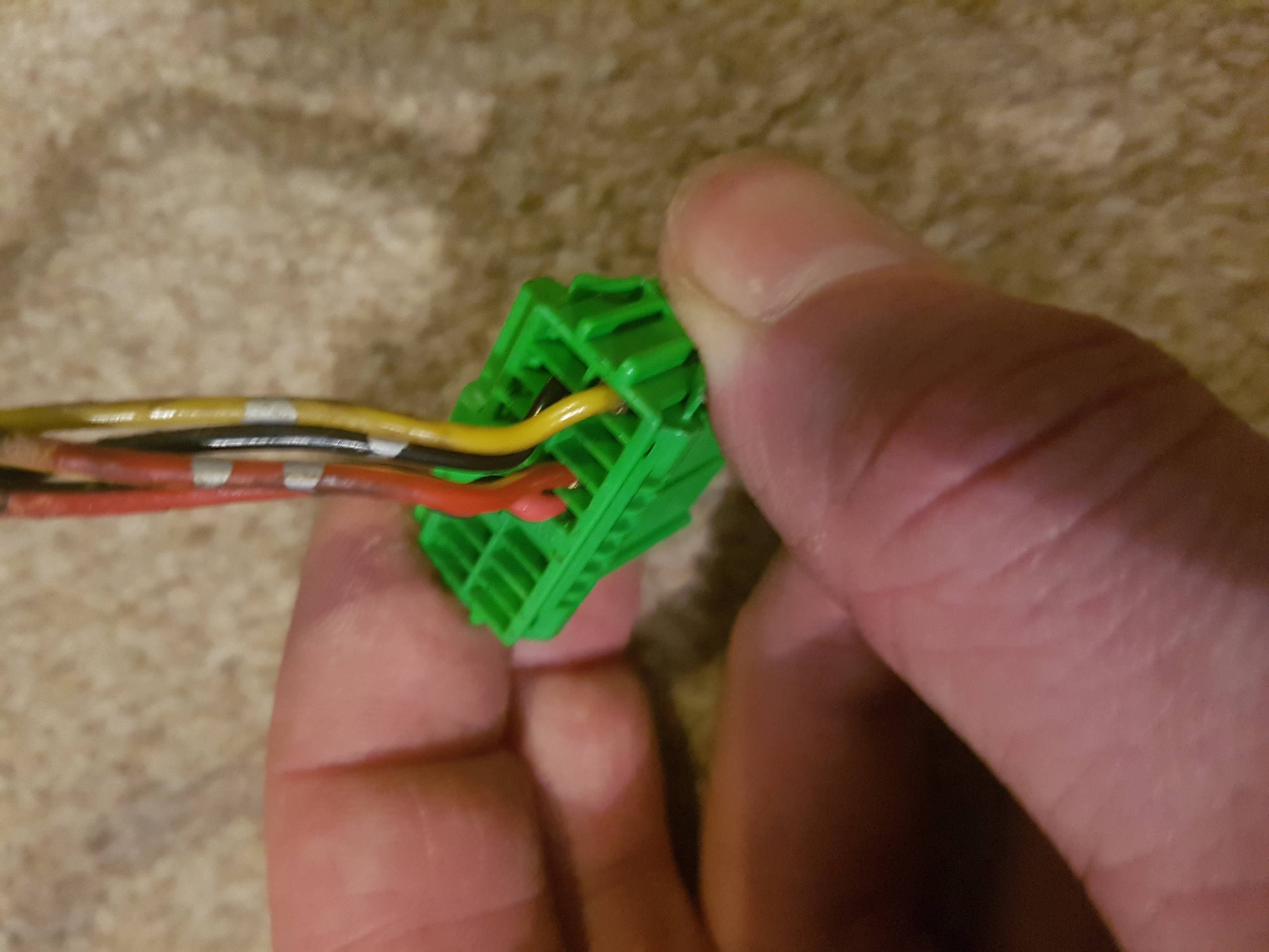
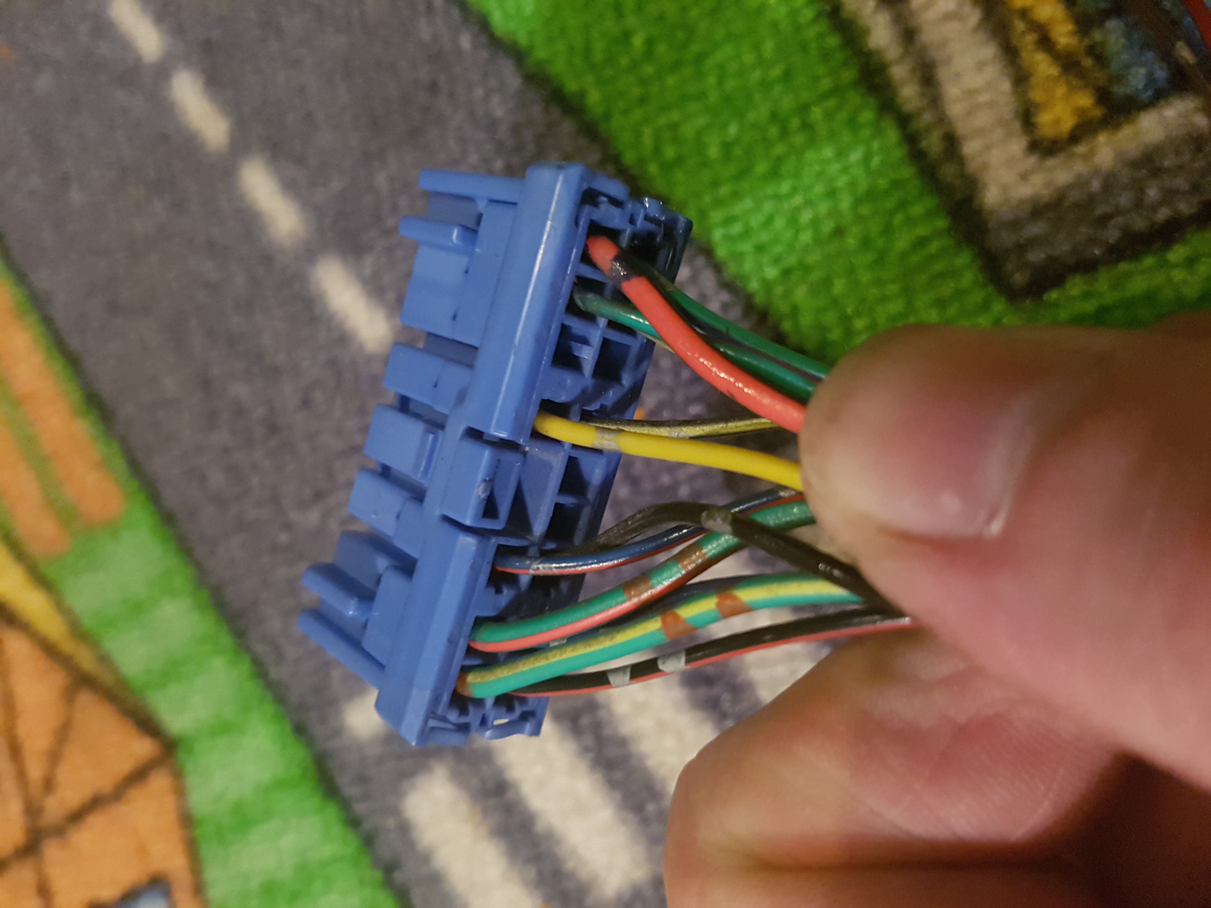
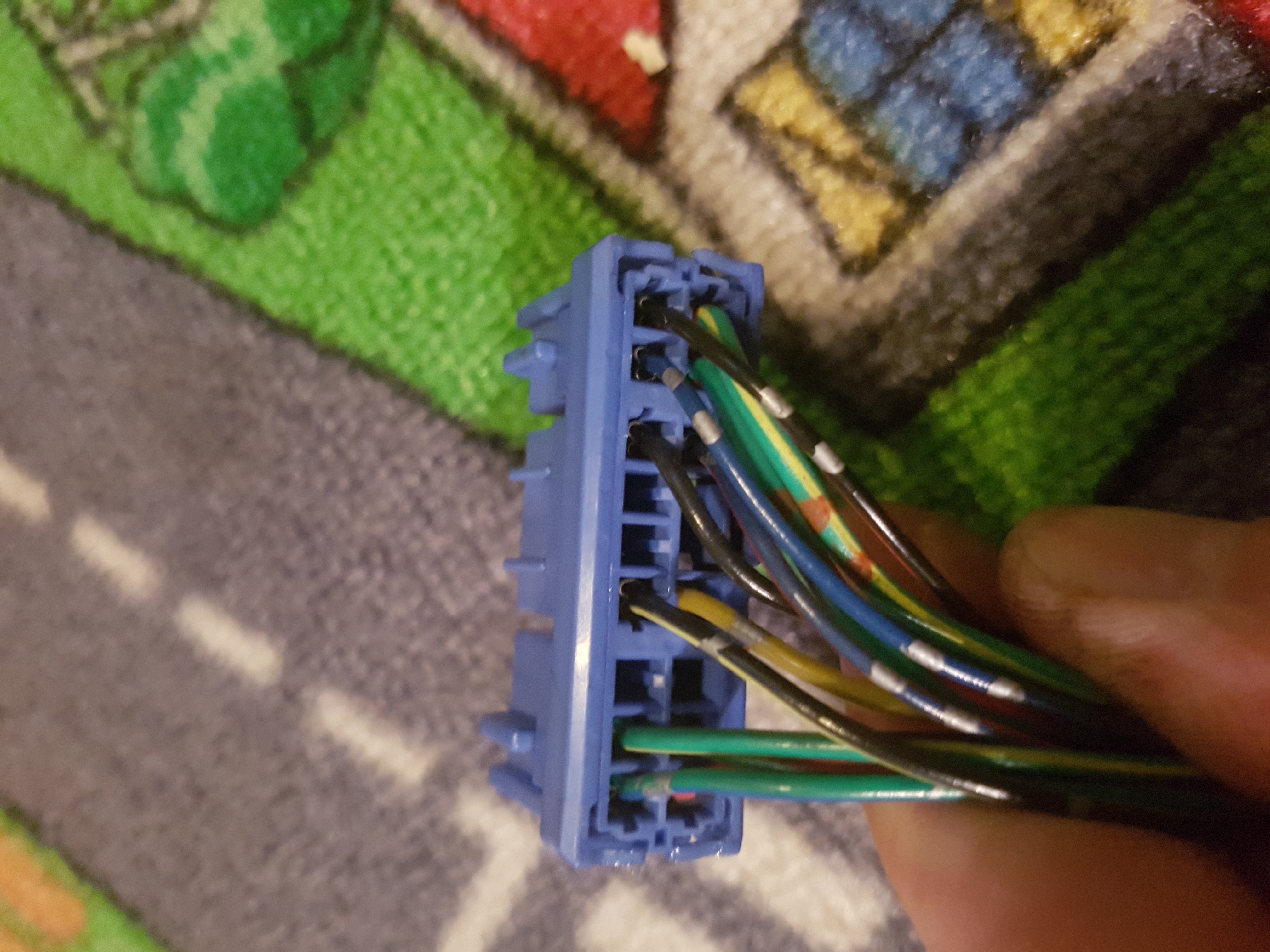
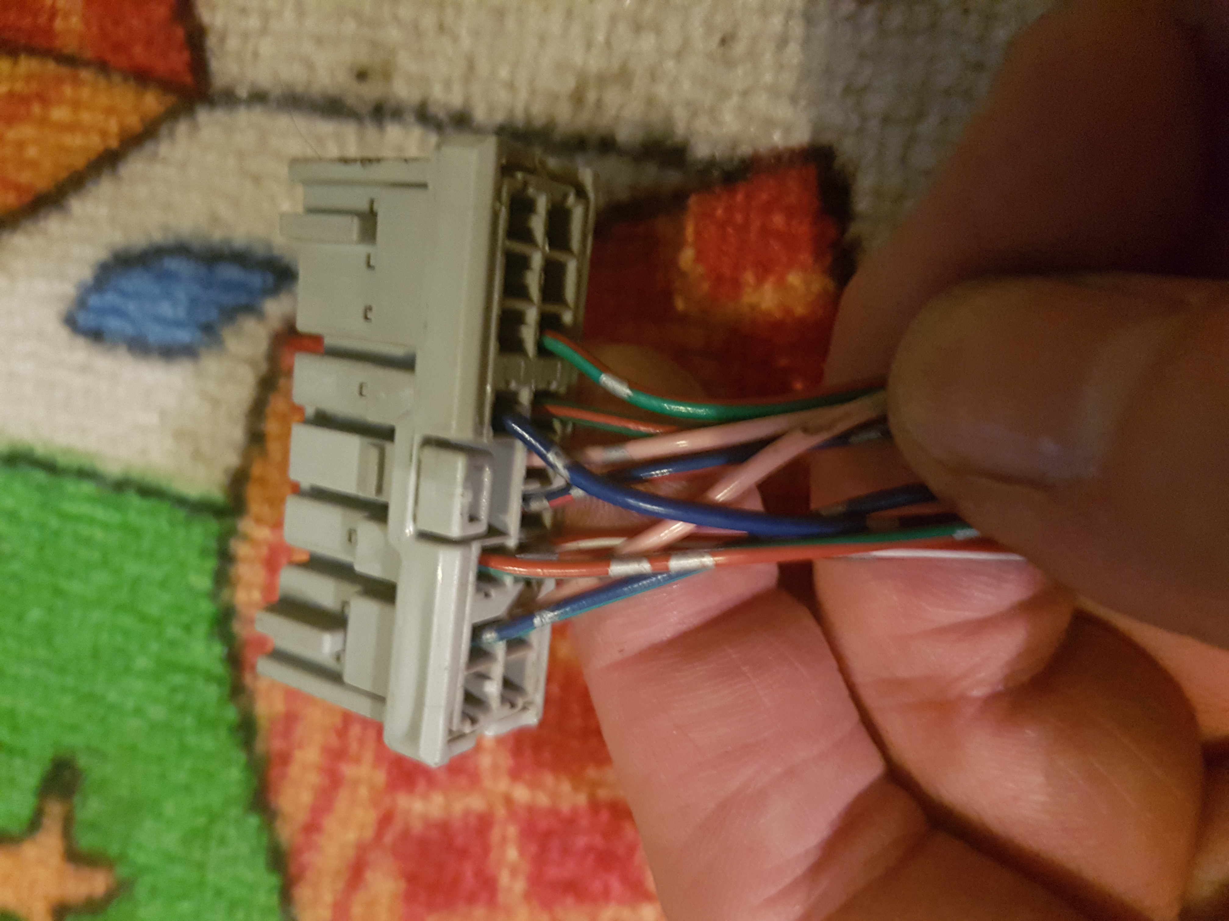
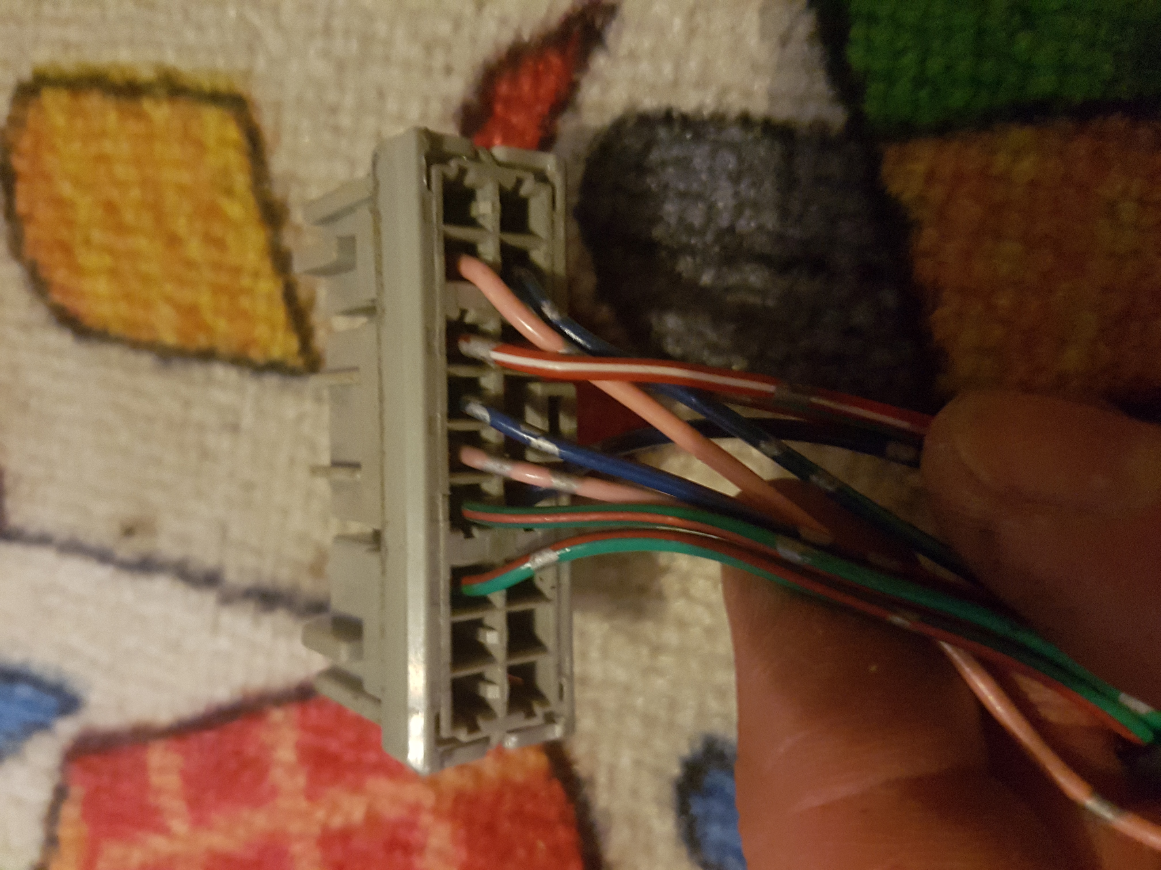
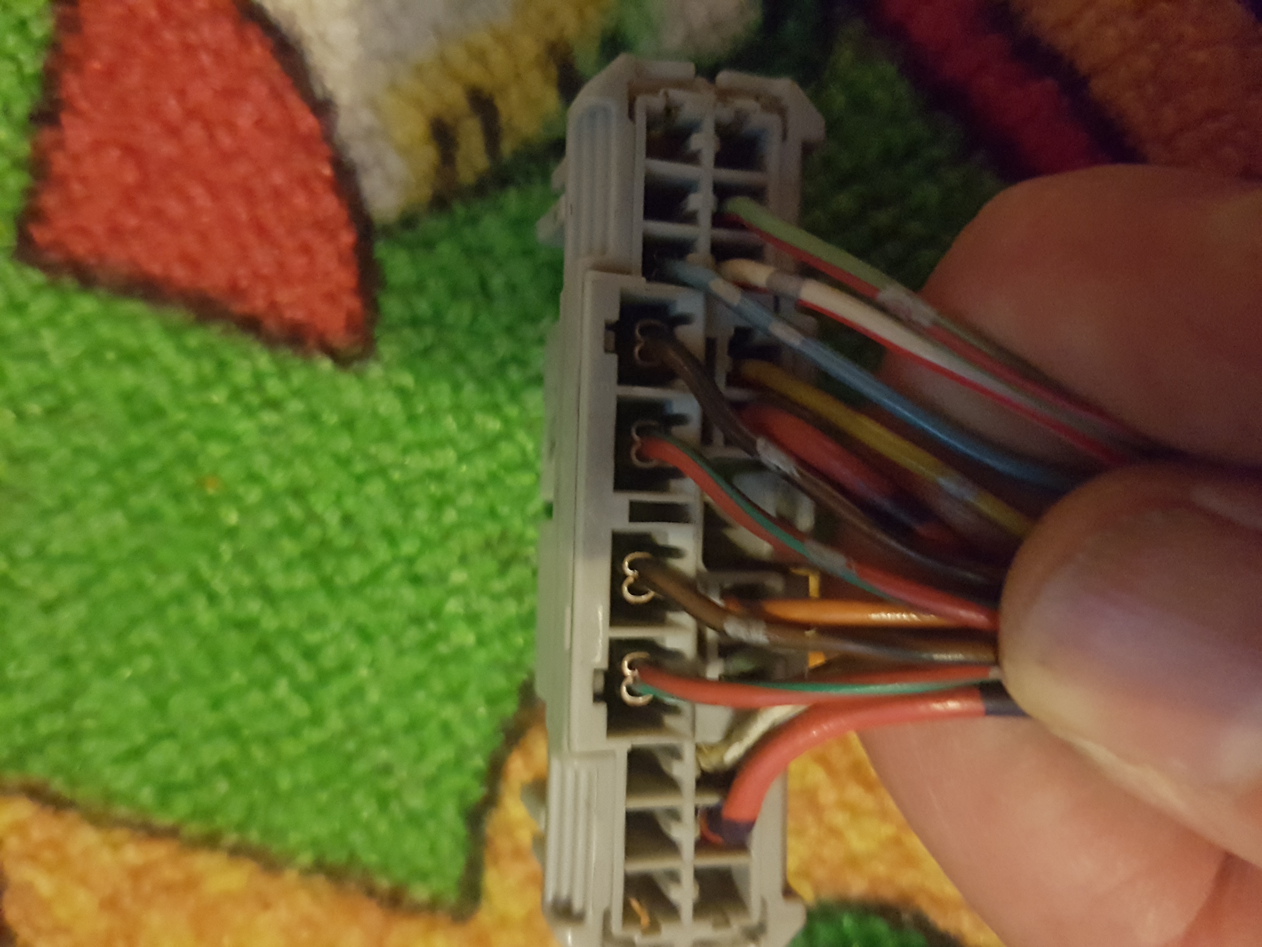
Pictures of how the plugs and wire colours should look:
Plug 1 bottom single row - temp & Fuel

Plug 2 top view - temp & fuel
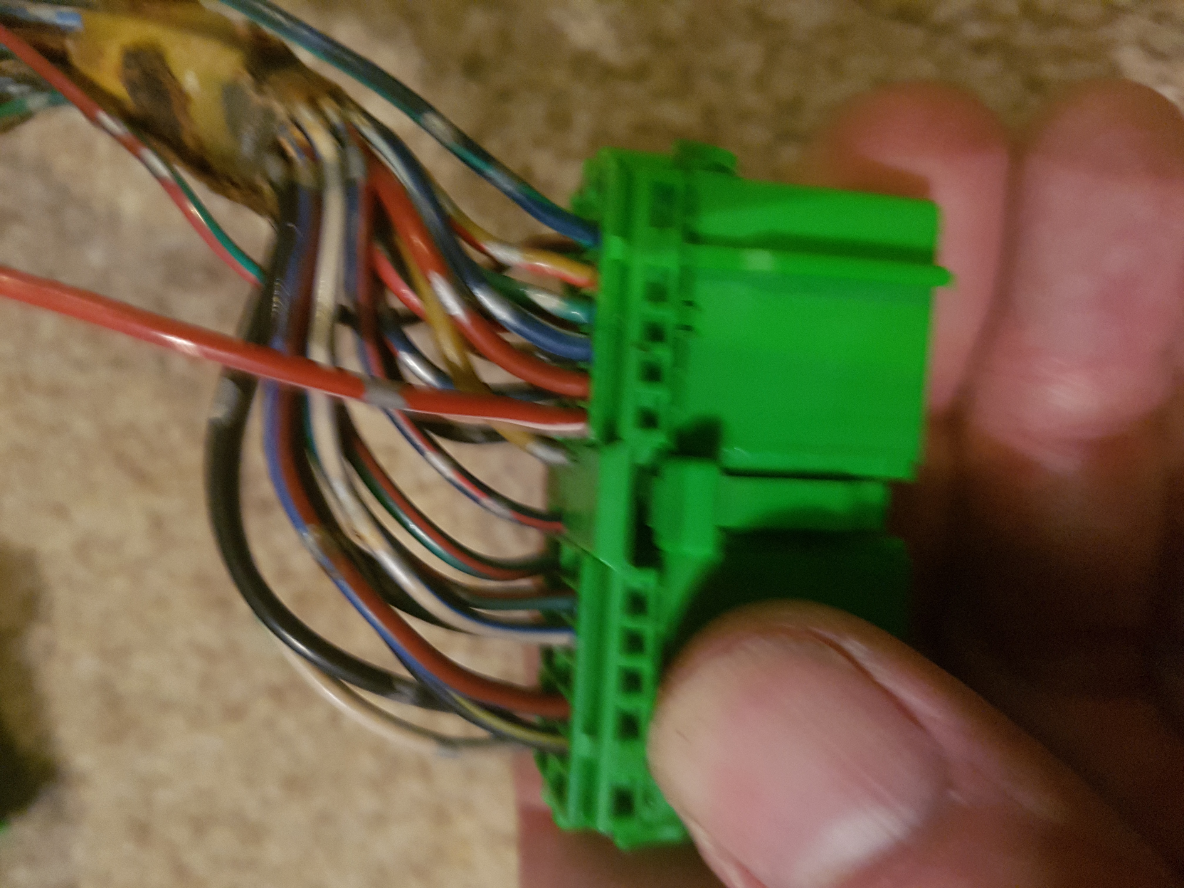
Plug 2 bottom view - Temp & fuel
Plug 3 (shouldnt need any changes) - EL Dials
Plug 4 - EL Dials
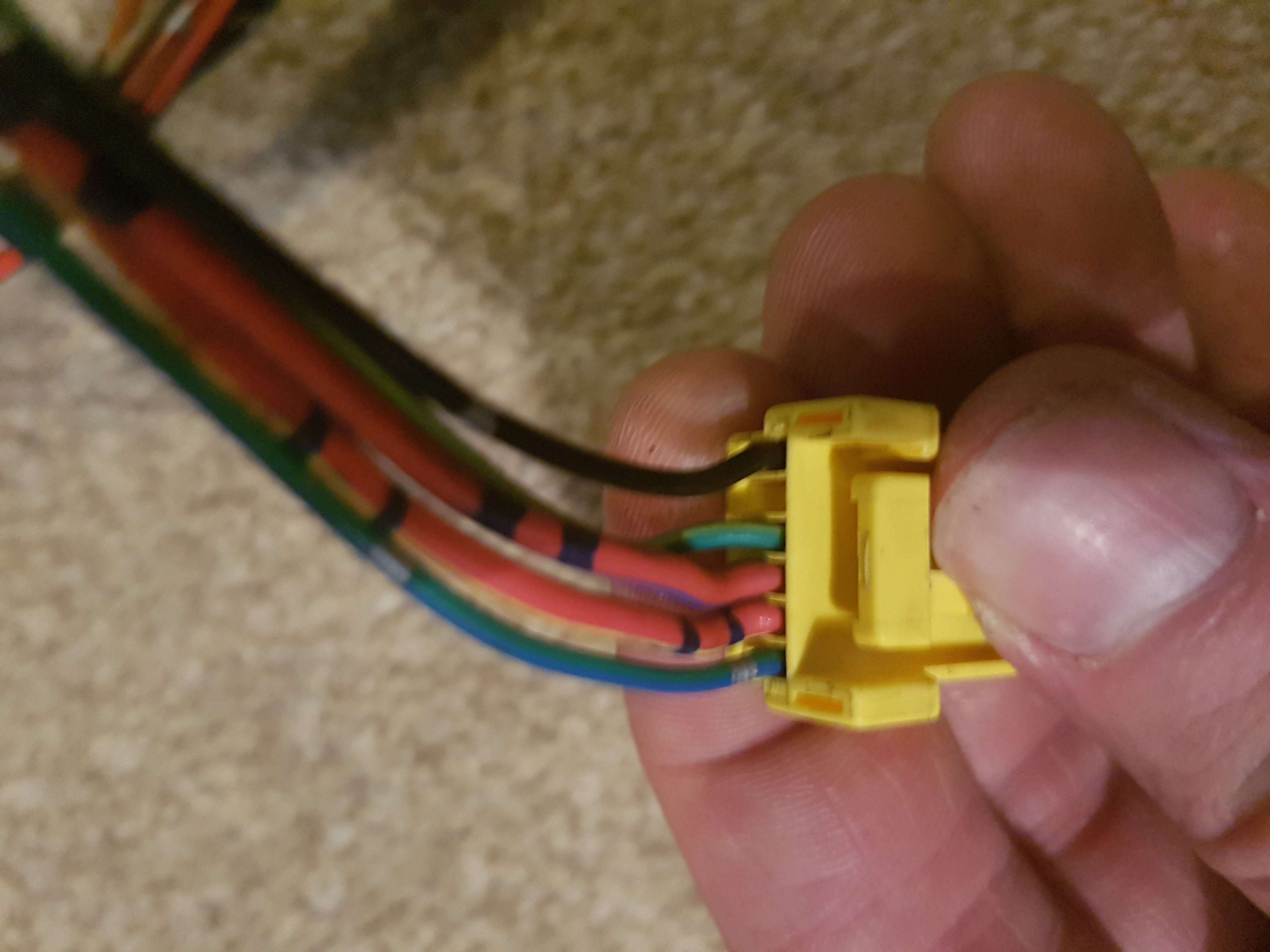
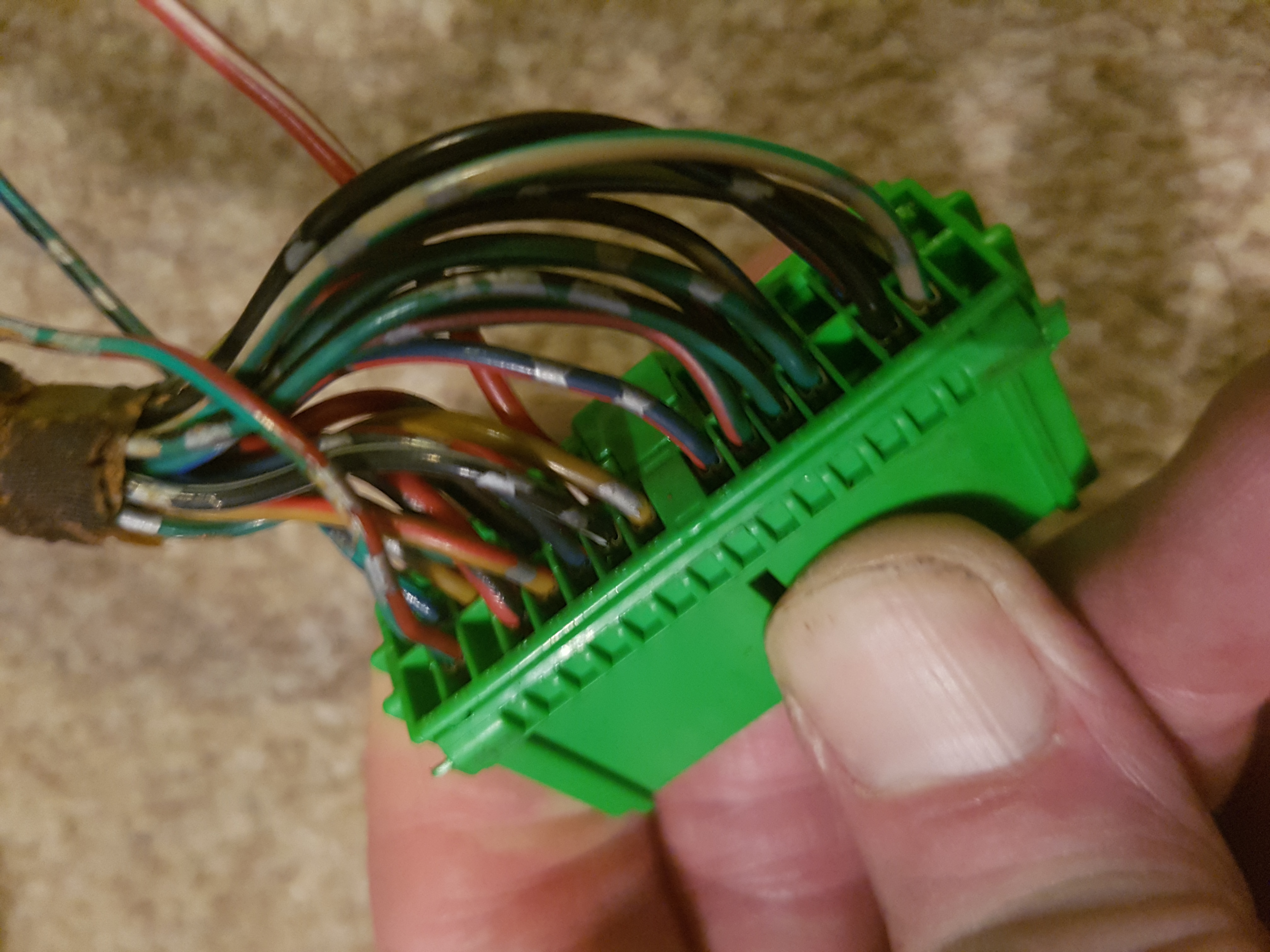
Plug 5 top view - EL Dials
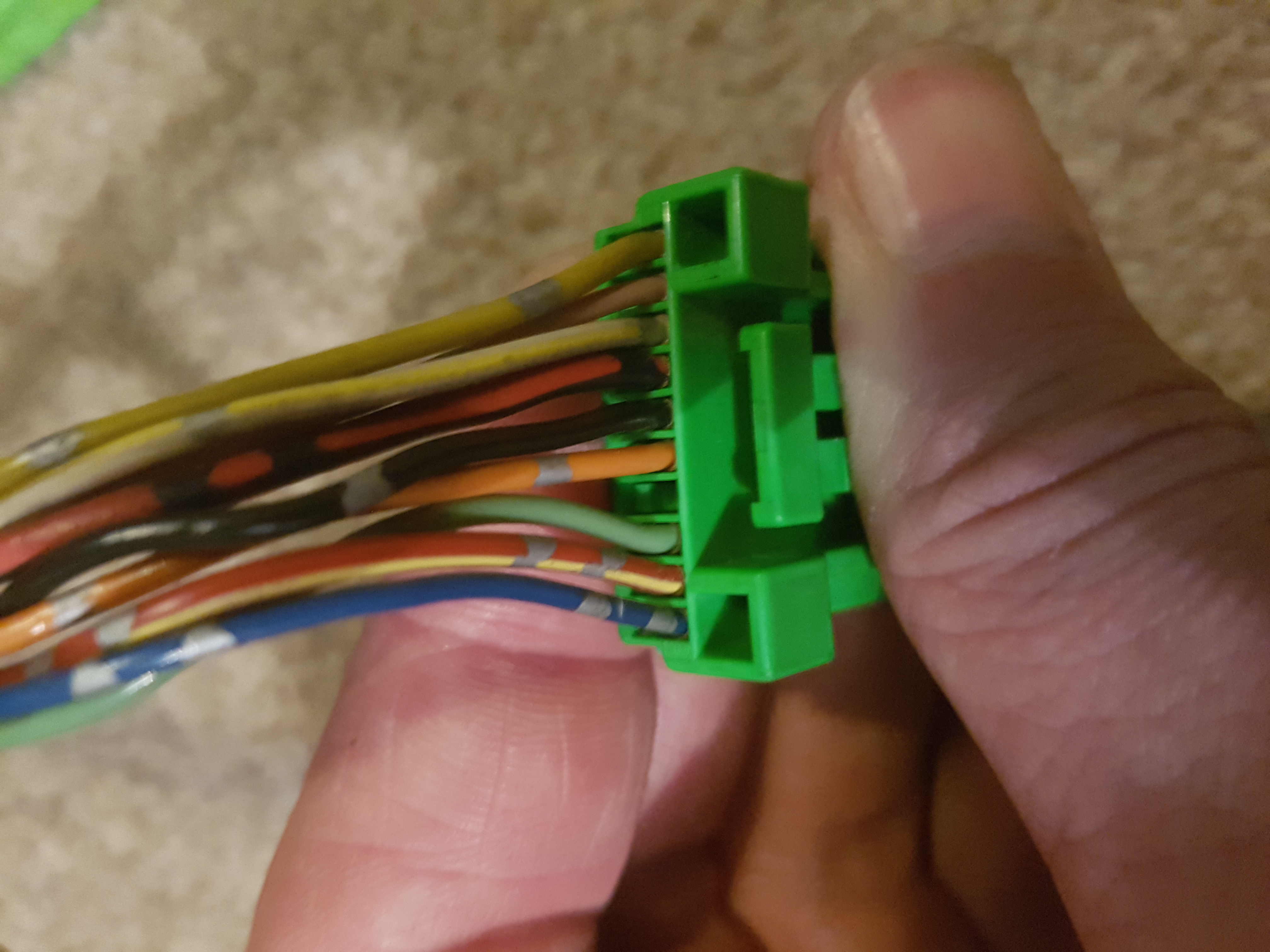
Plug 6 Top View - Driver footwell
Plug 6 Bottom View - Driver footwell
Plug 7 Top view - Driver footwell (short)
Plug 7 Bottom view - Driver footwell (short)
Plug 8 Top view - Driver footwell (long)
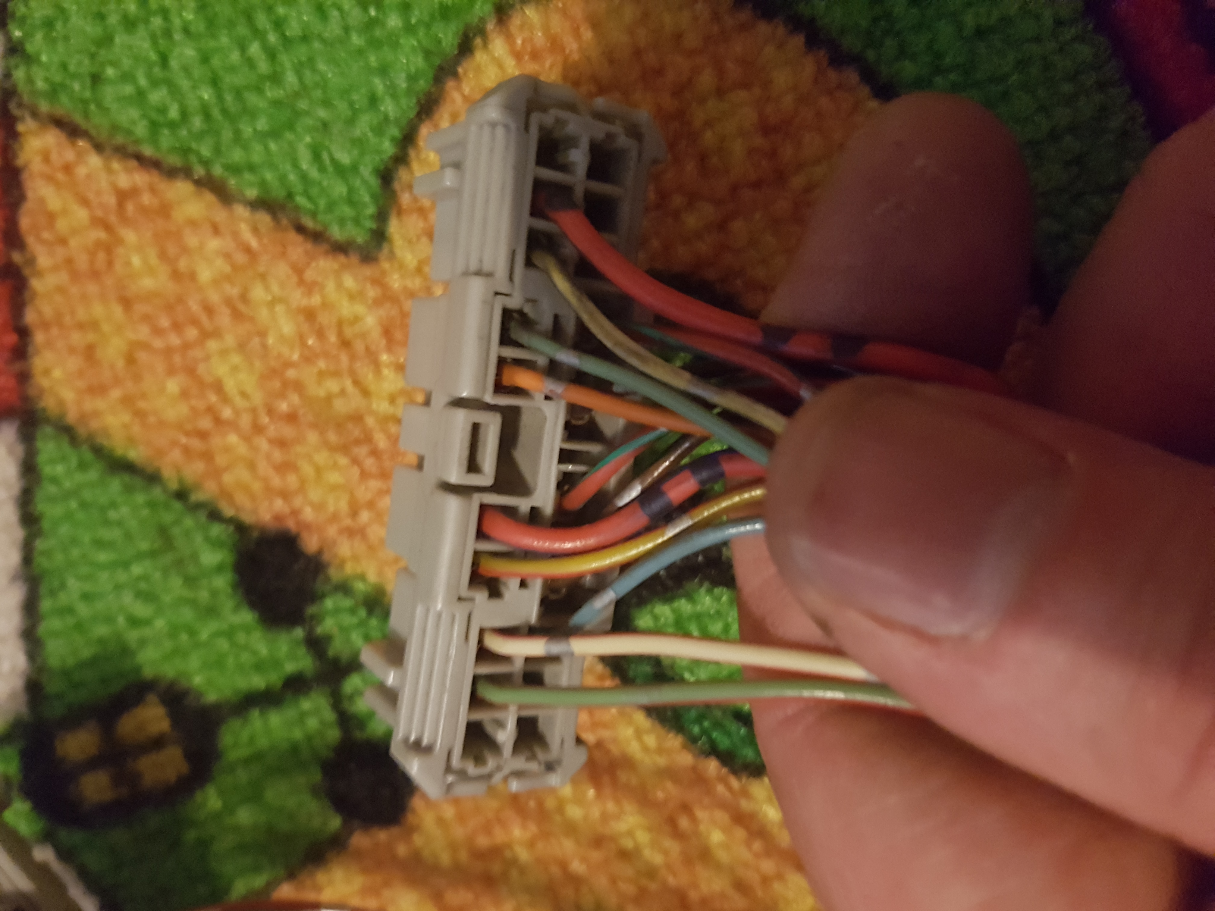
Plug 8 Bottom view - Driver footwell (long)
(also i forgot but move over the temp wires also)
there is a tracer wire that you will need to plug into the yellow splitter box. This was fun now the facelift splitter has smaller wire connectors than the pre facelift however with a little ingenuity i used this
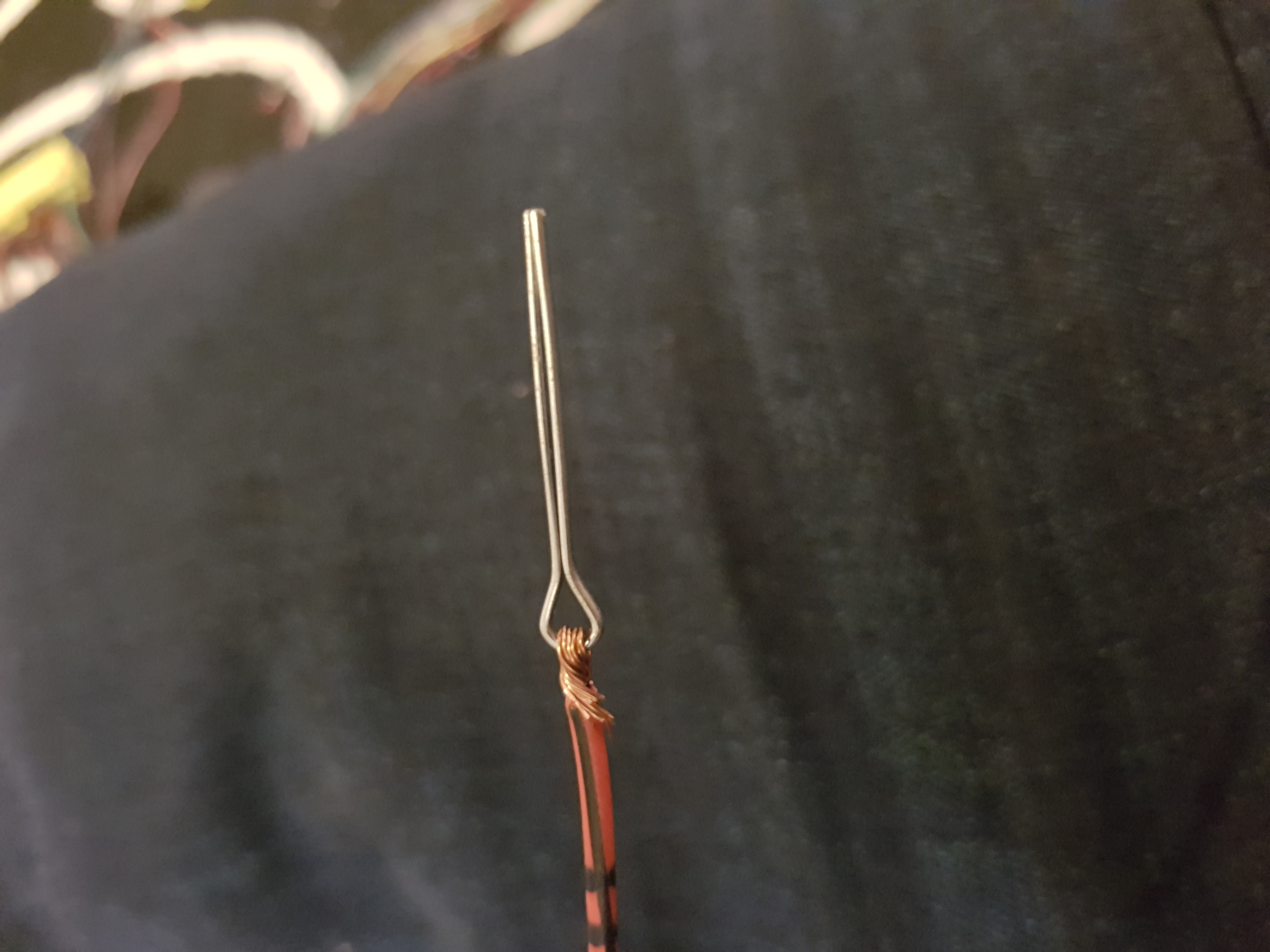
held in place i plugged the splitter end of the plug back on and it held securely in place. Lots of electric tape.
Now you should be ready to test.
before you tidy up the loom plug into the footwells and make sure all is working.
You will have an extra earth wire this will need to be earthed to the car for the indicators and lights to work correctly.
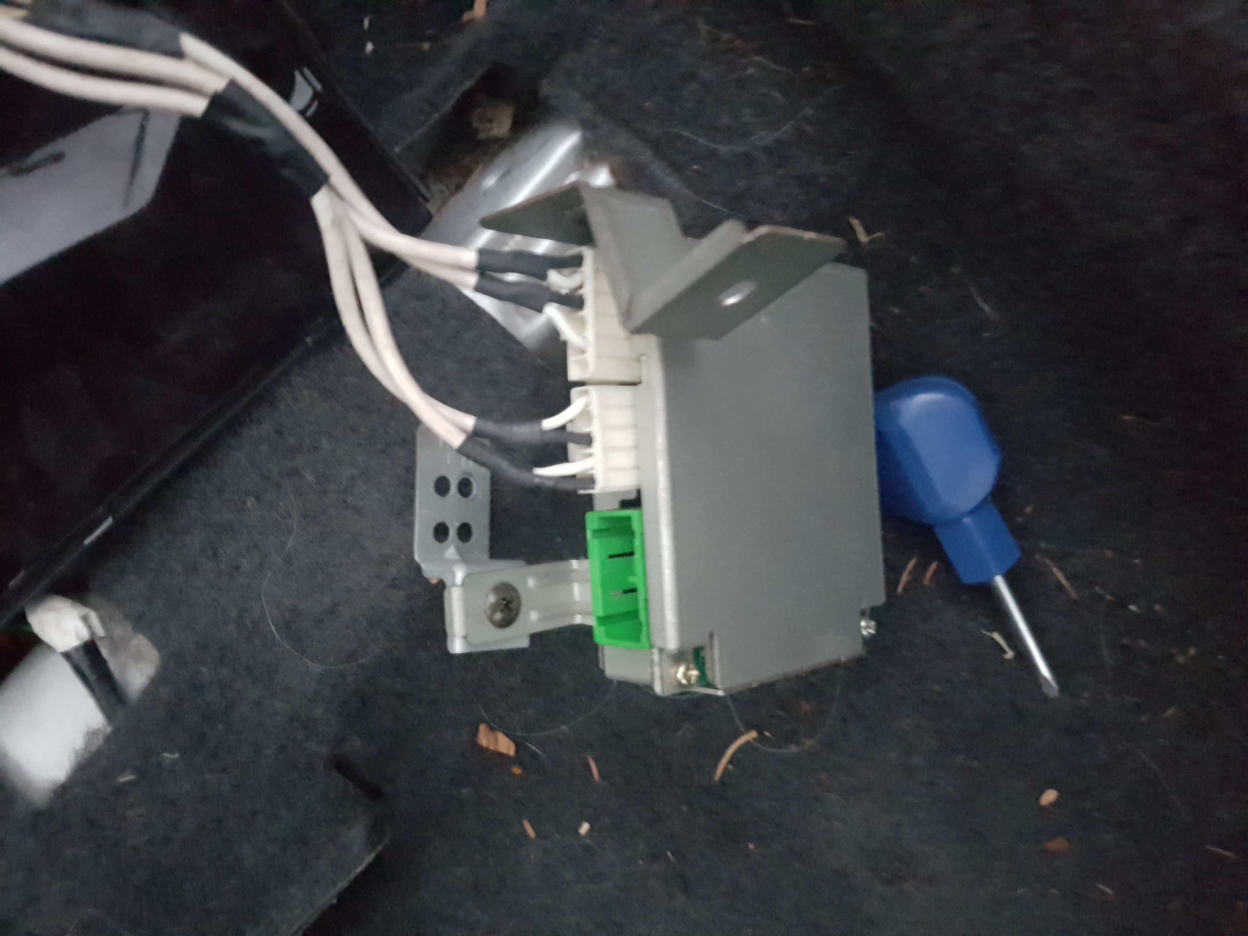
Some troubleshooting was needed. My car does not have a dimmer as standard and as such i had issues with the dimmer box and plug.
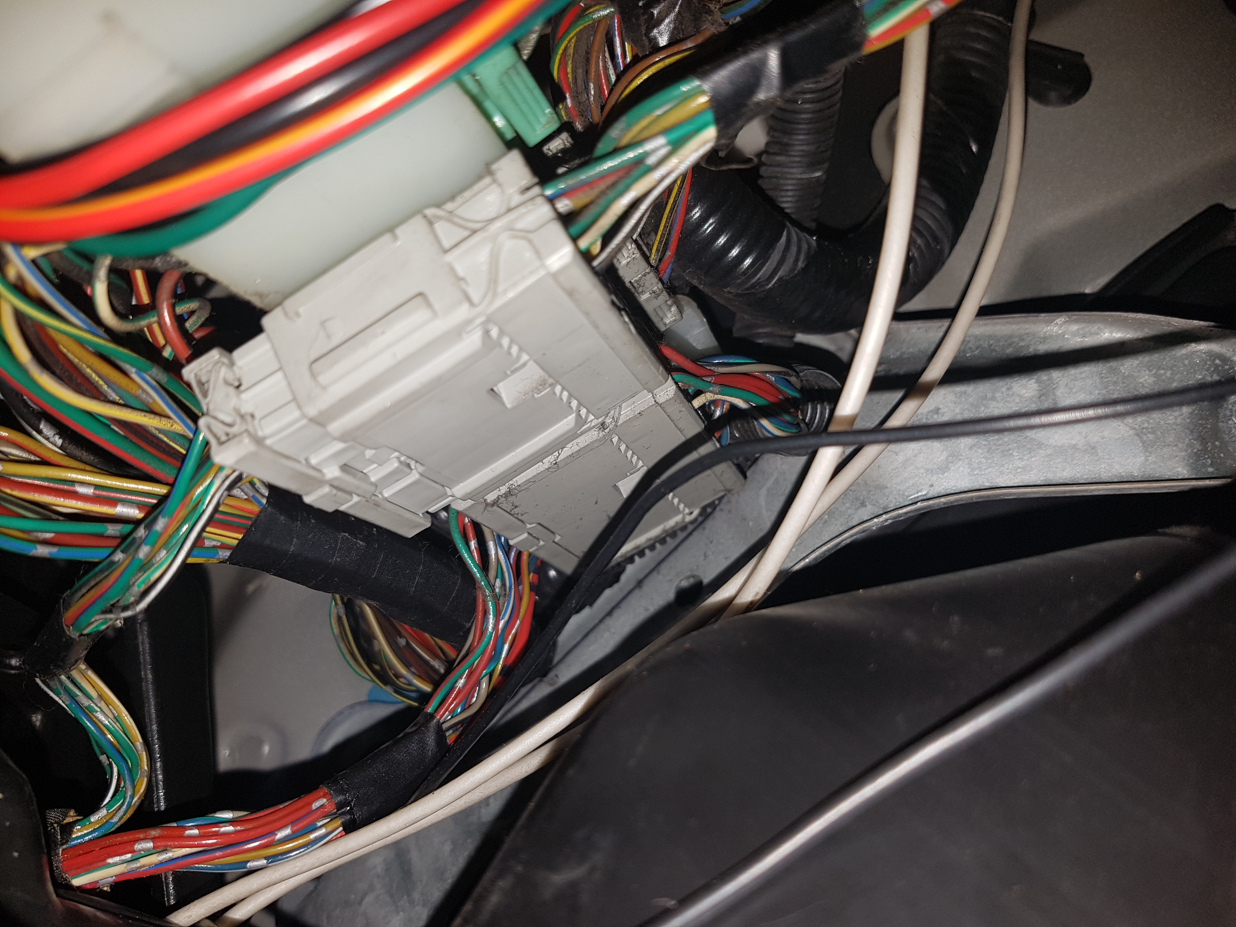
this was how it all looked
all i done to rectify this was remove the dimmer box (im assuming because i dont have the dimmer switch attached it was causing an issue.
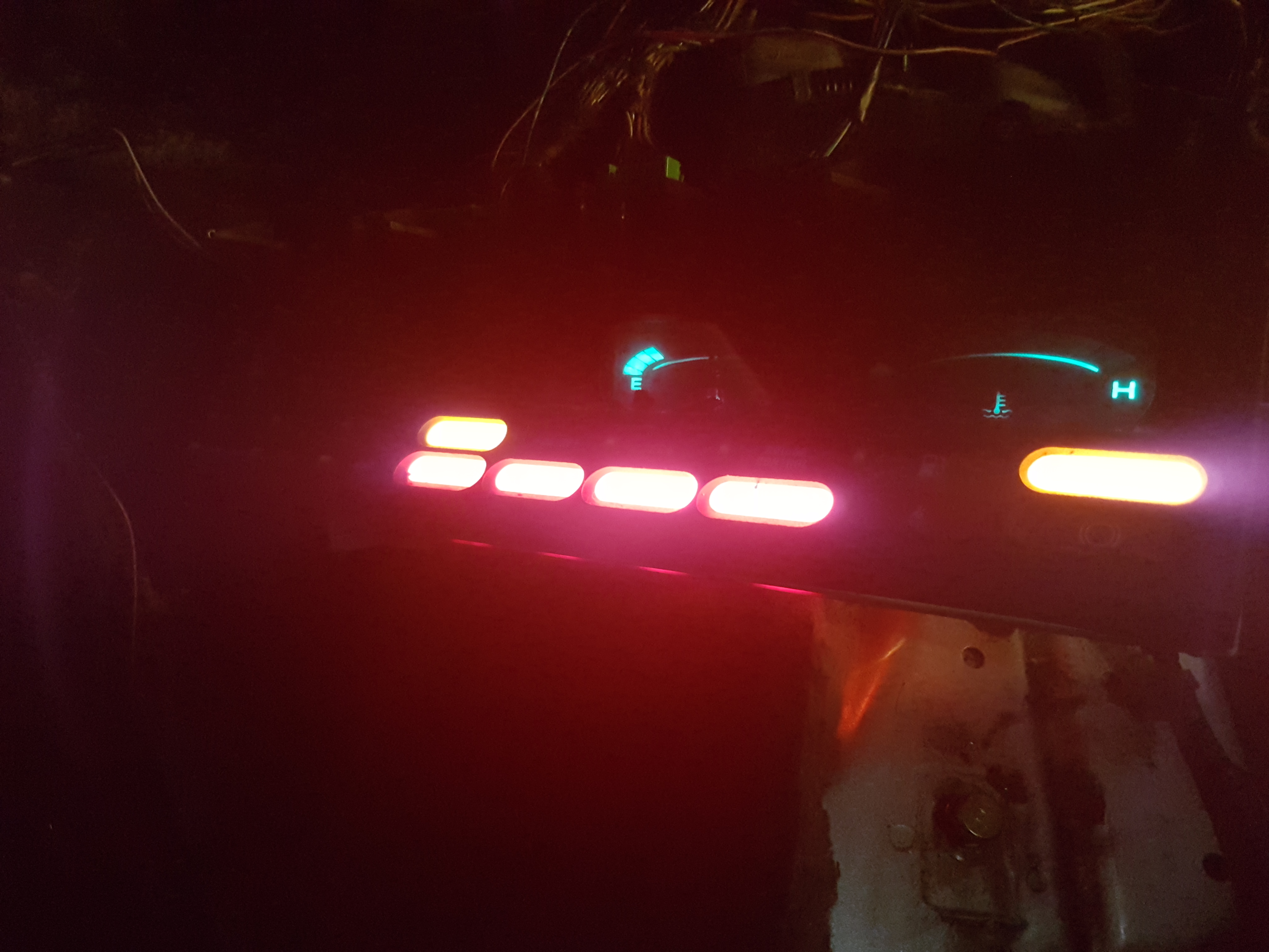
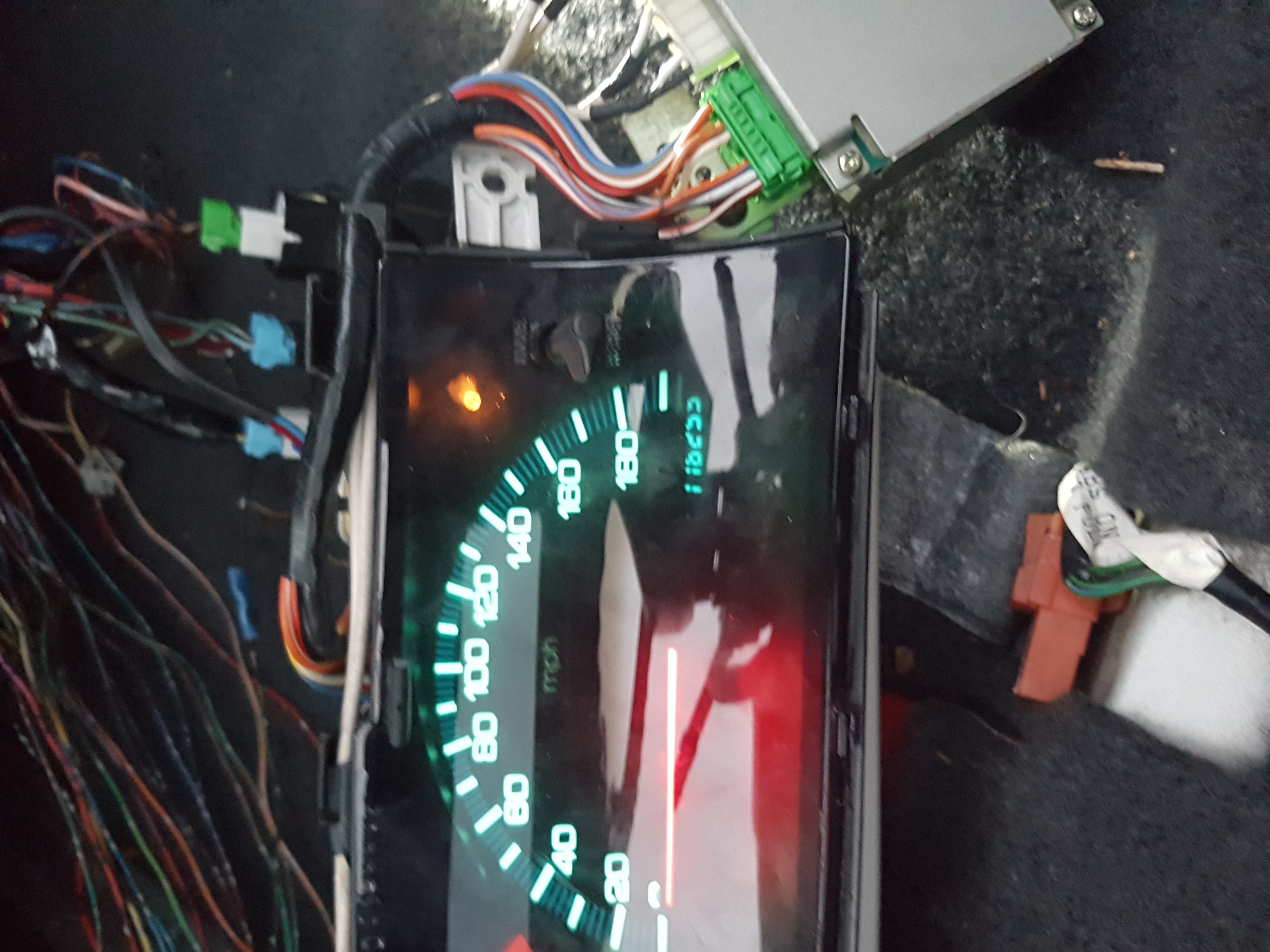
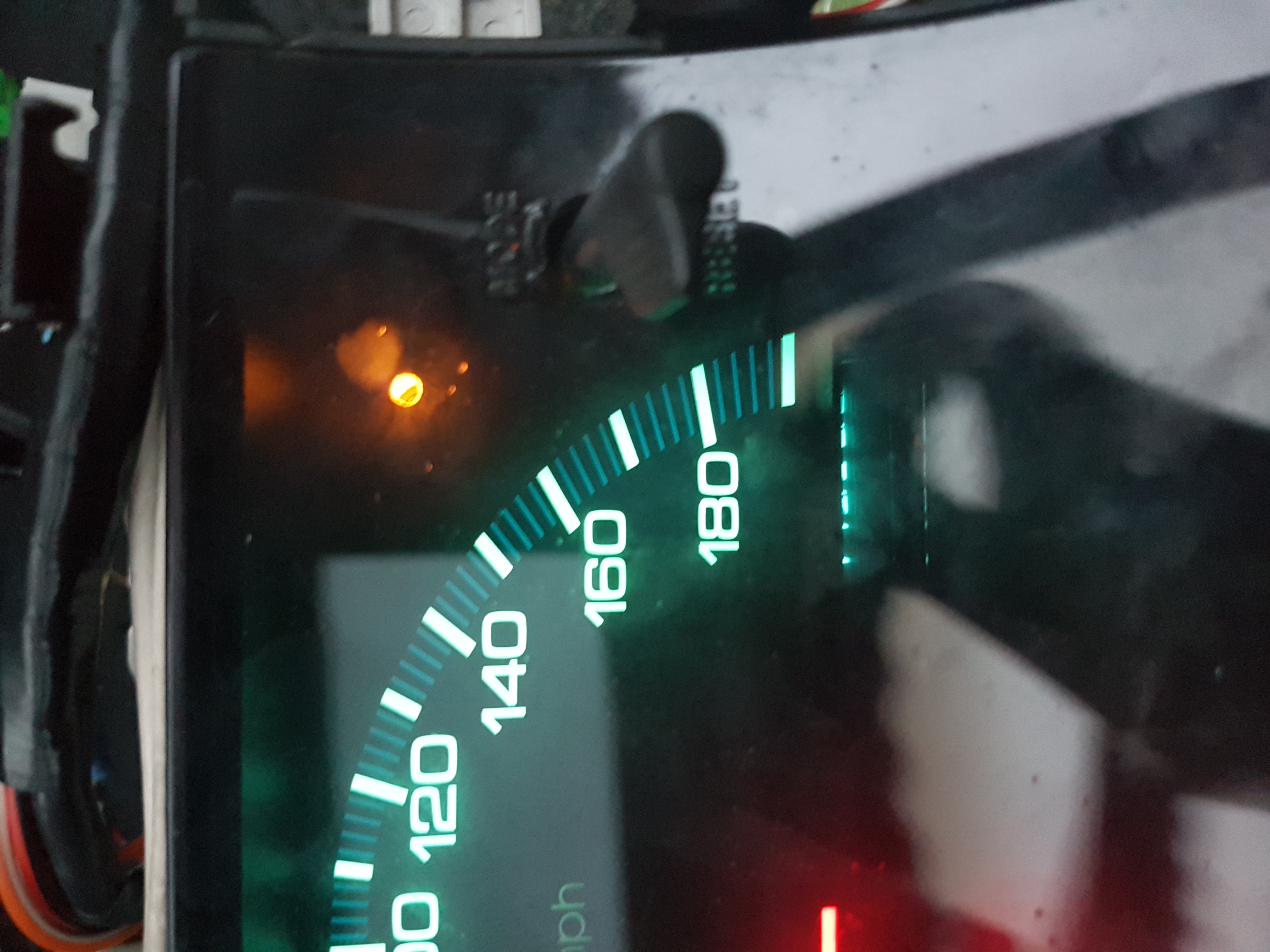
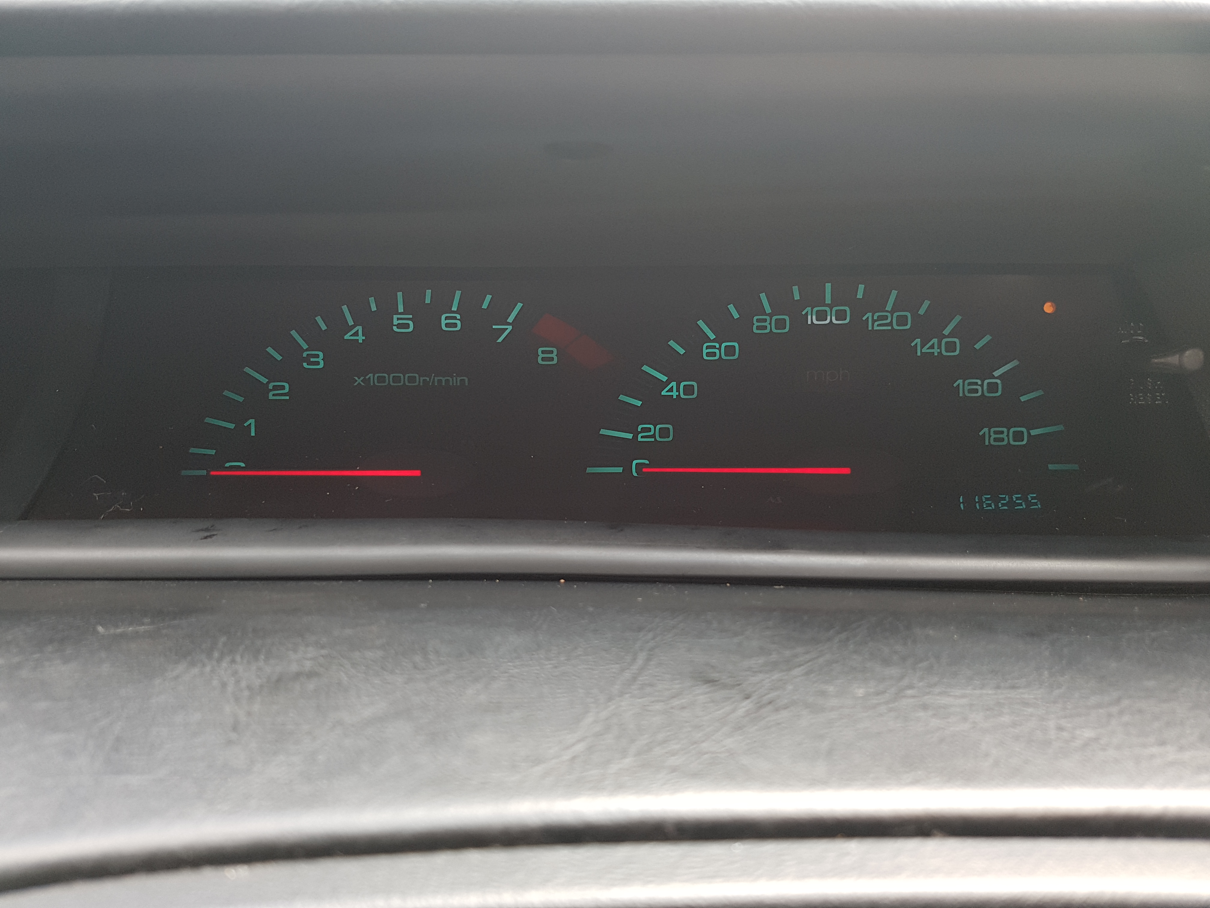
I them had life
well some...as you can see no EL speedo or rev lights (trust me at this point i was like what the god damn drokking son of a gun)
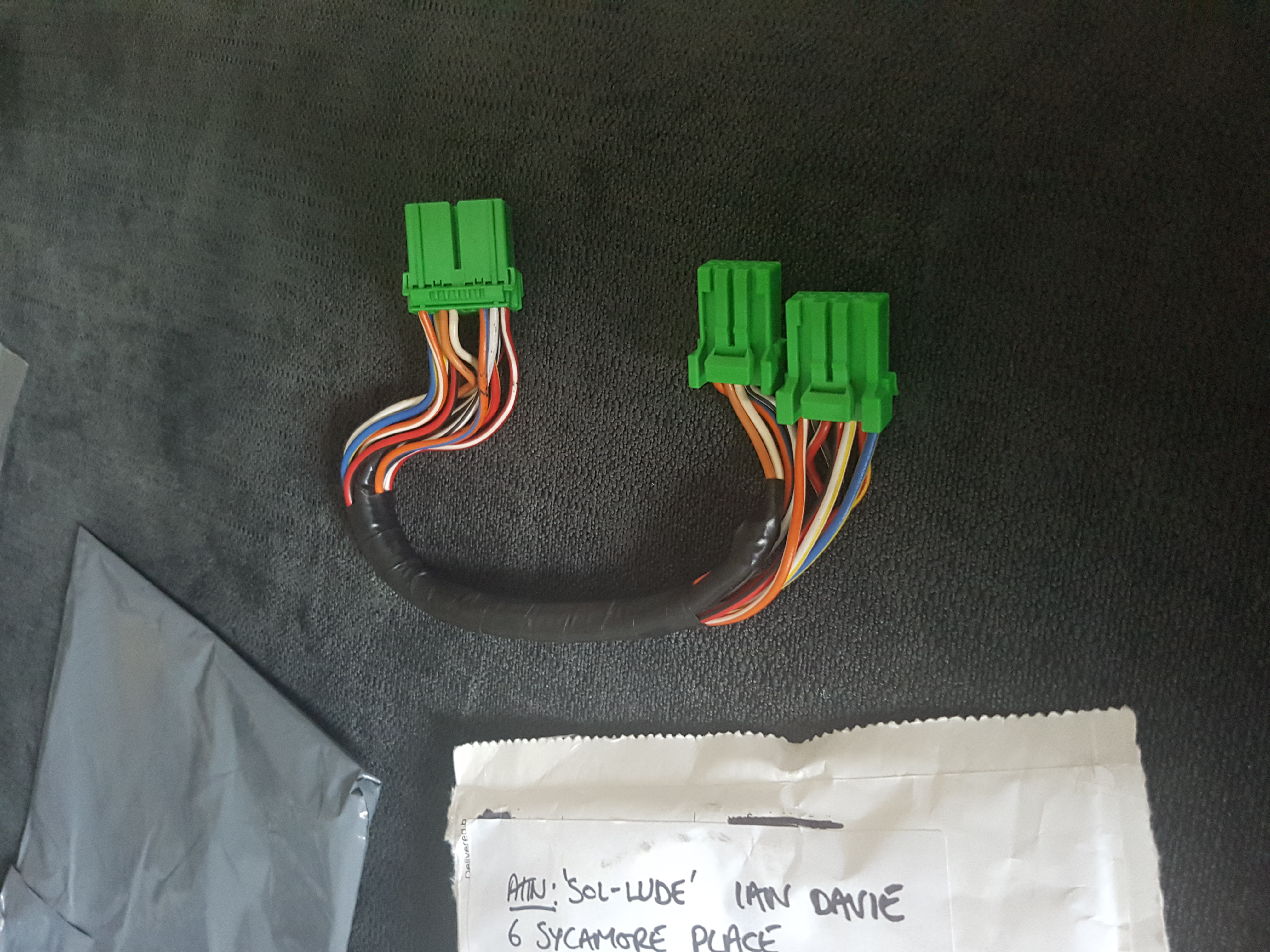
This was an easy fix and a mahoosive thank you to bennyboy it seemed i was missing a harness for the EL dials that connect to the inverter.
Bennyboy hooked me up with his spare harness and had it the next day so thank you so damn much mate.
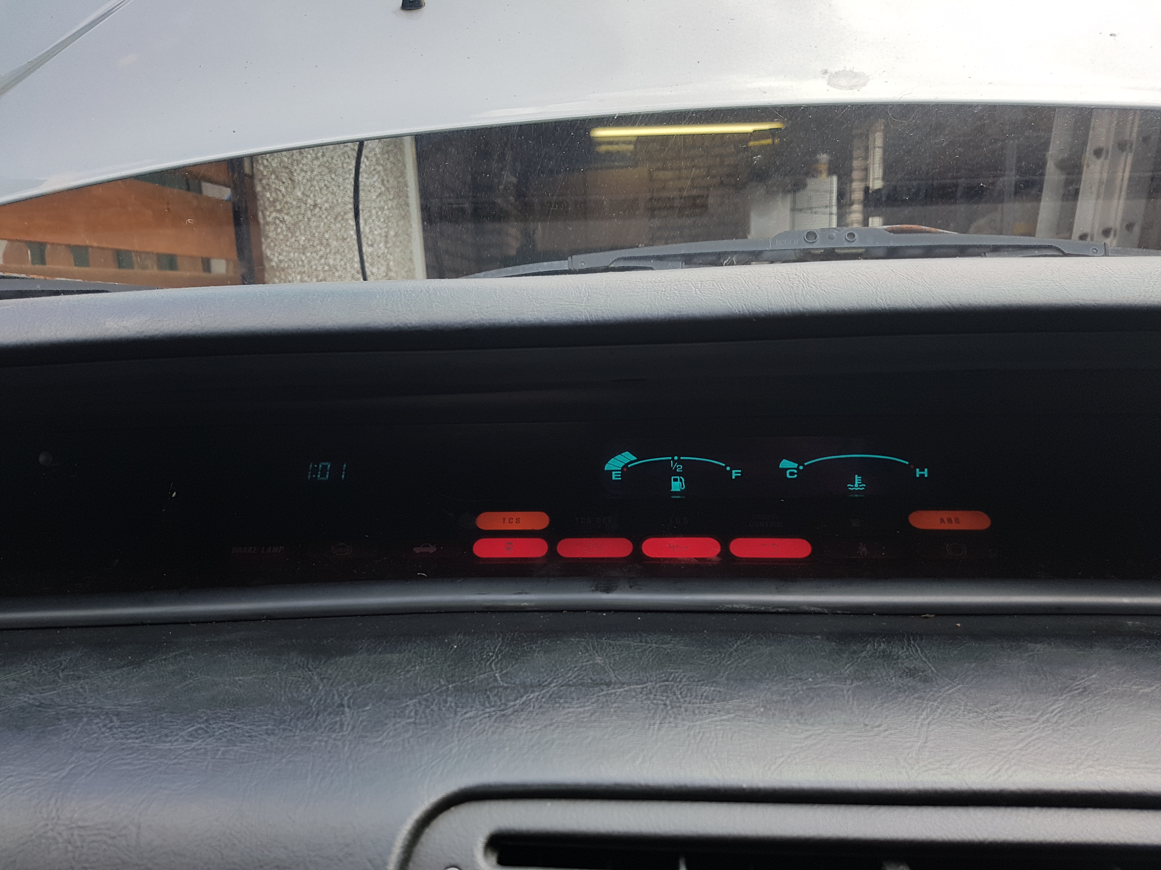
plugged it in an voala
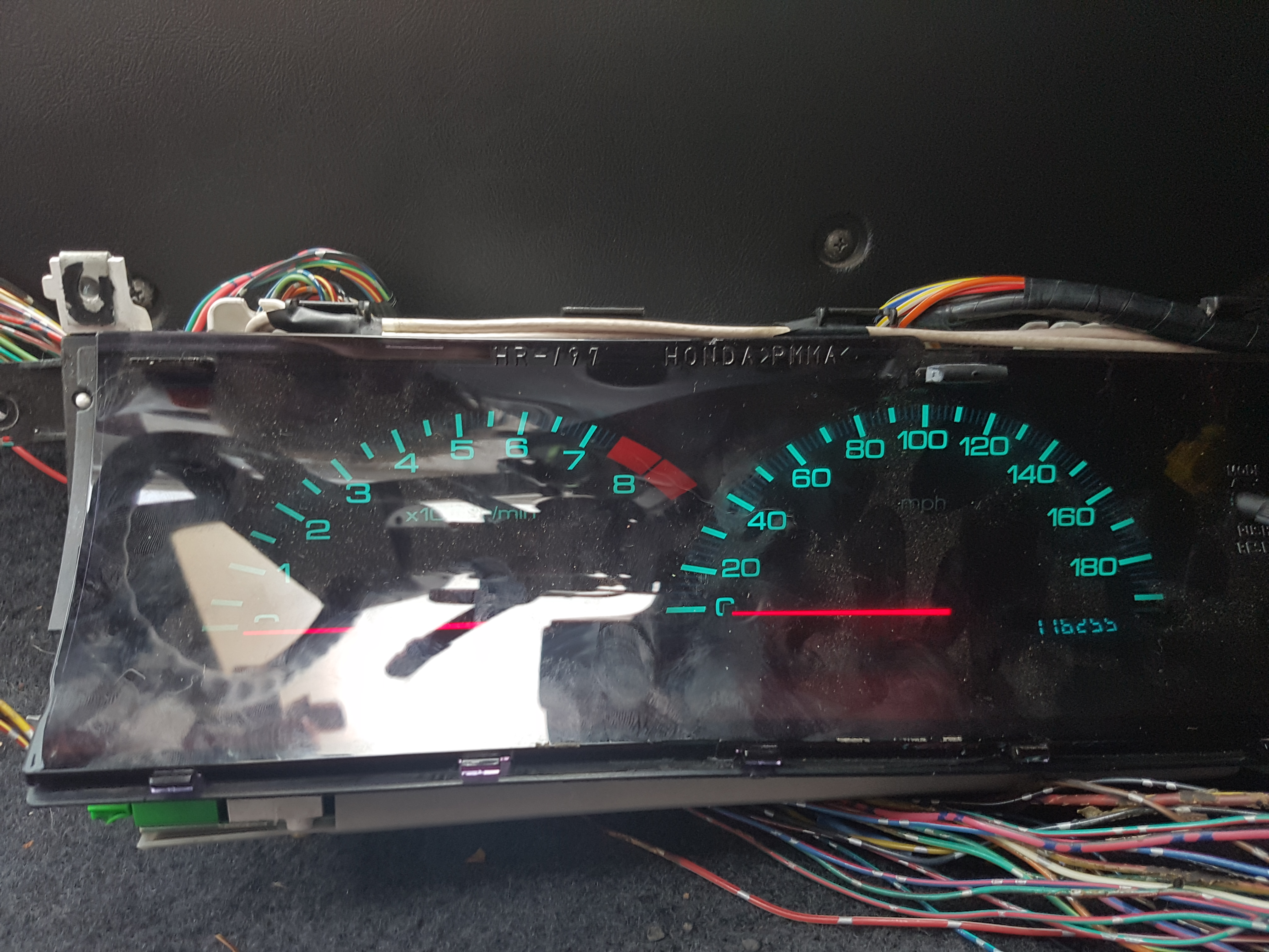
now before i could put all back together i had another issue. The 4WS warning light ... i shone a light through but nothing so i decided...lets dismantle and see what i can do...
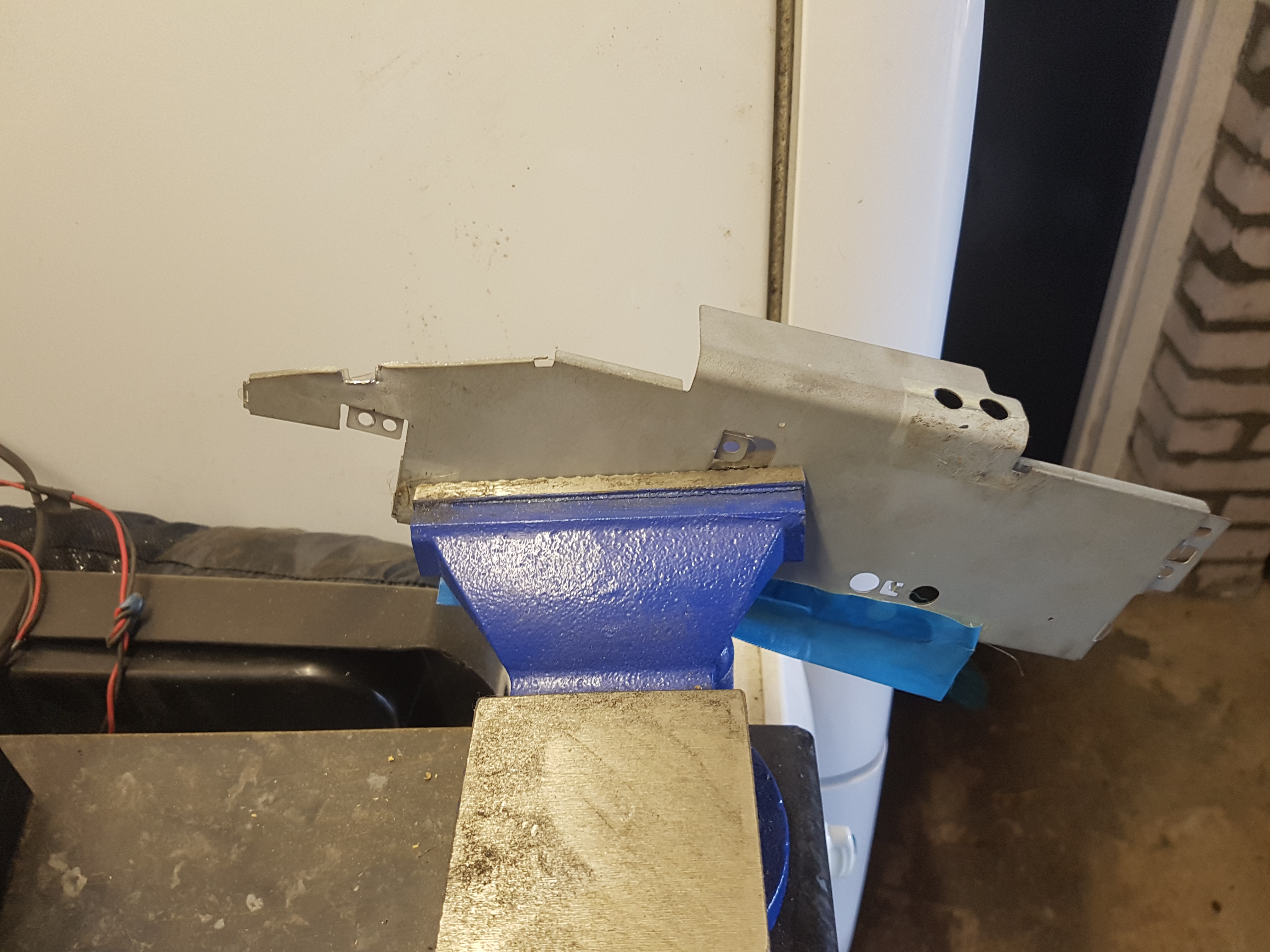
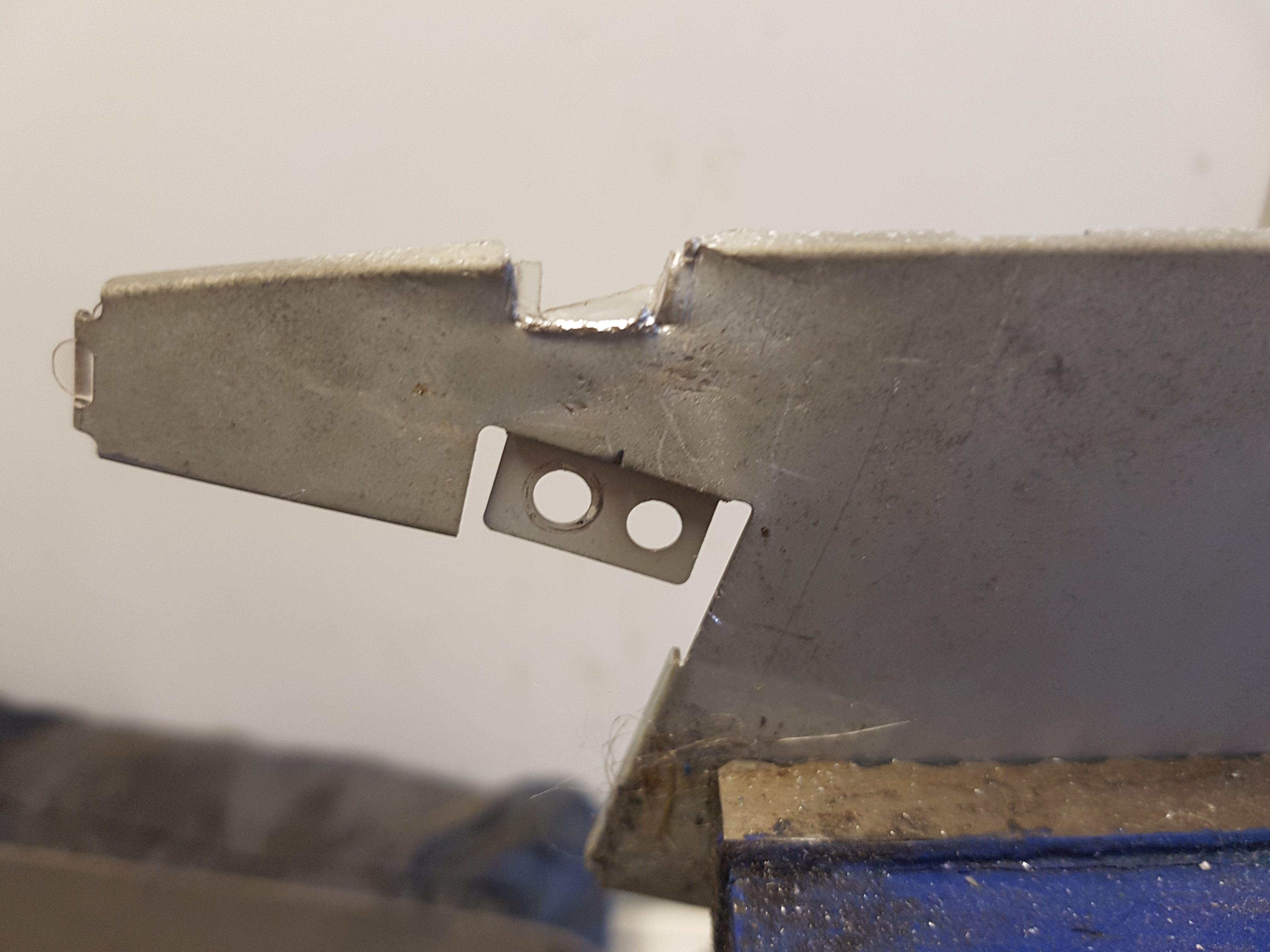
On the back of the EL dials there is a metal plate remove this and you will see the space for the 4WS warning bulb
now be very careful and preferably on wooden bench or unit.
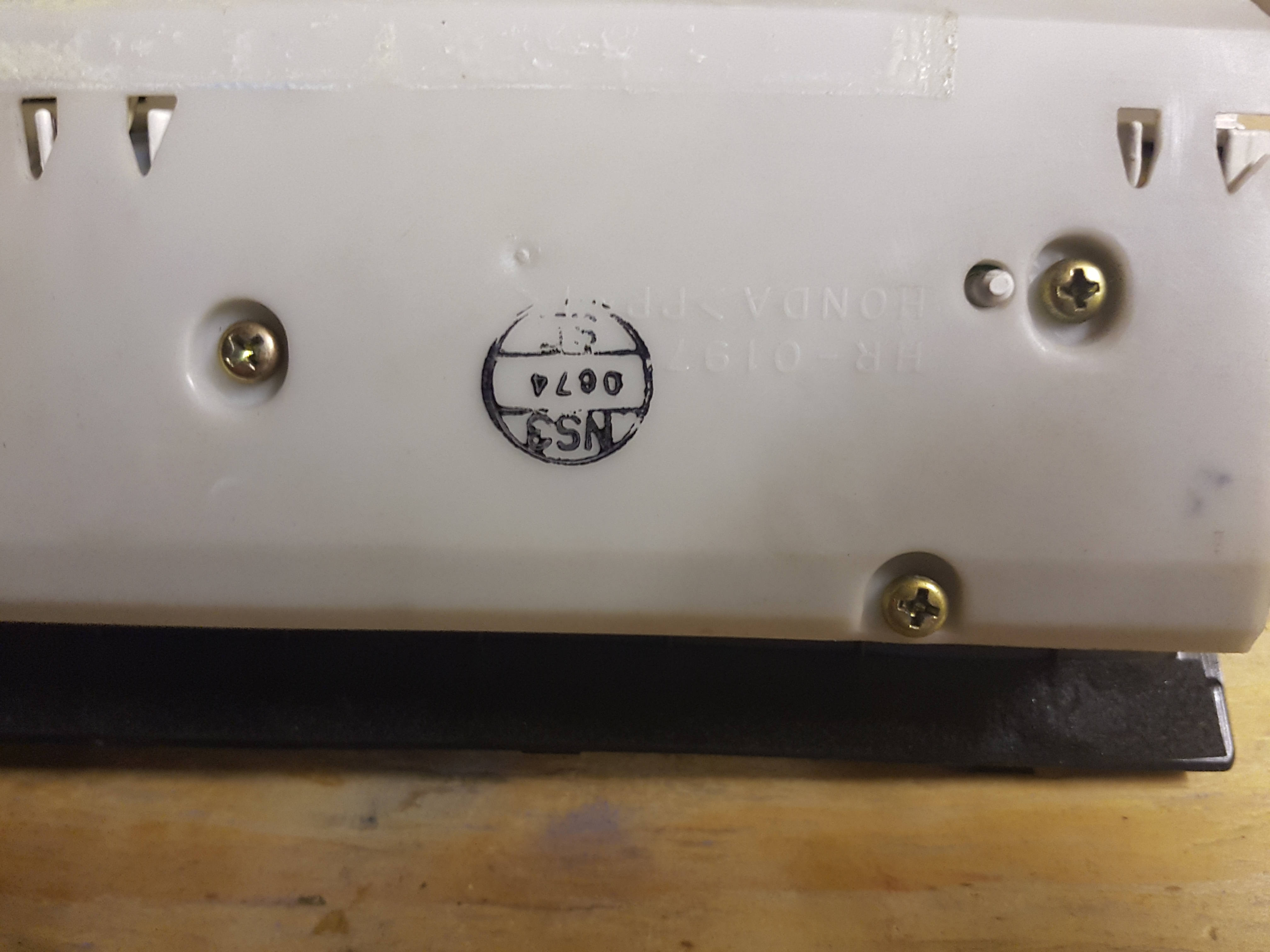
Remove the bottom white plastic
you will see two circuit boards
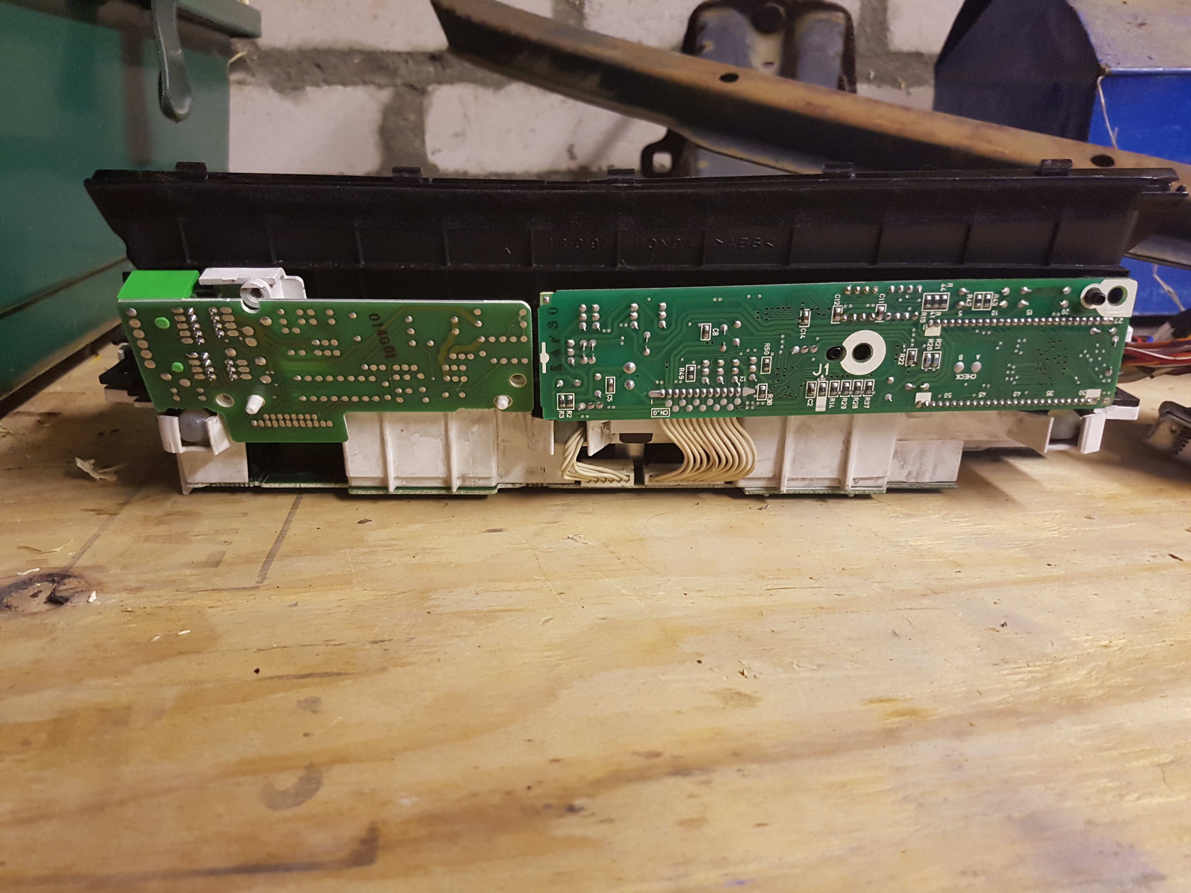
the one on the left not attached to anything
the one on the right has a small harness attaching to the dials remove this
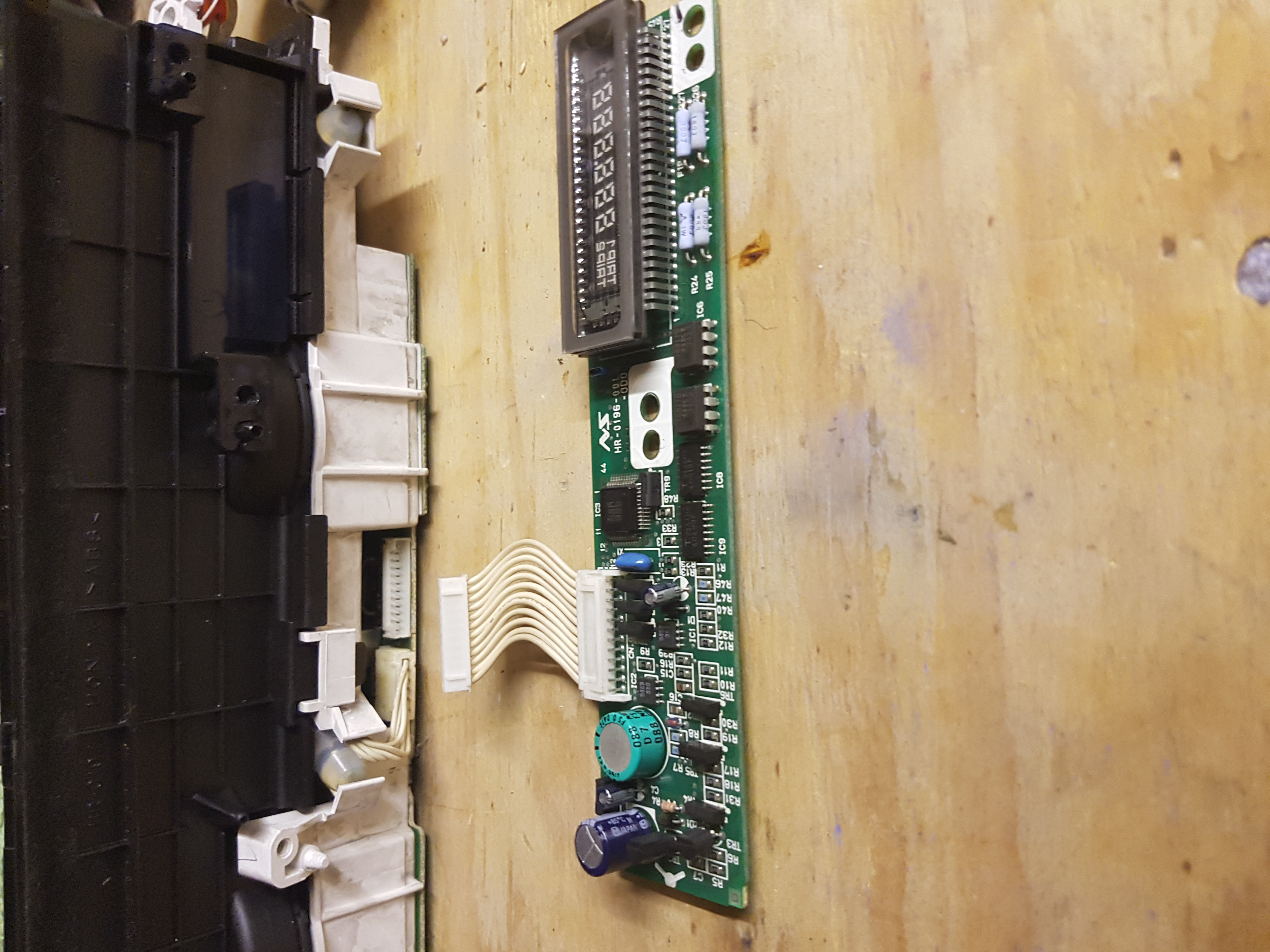
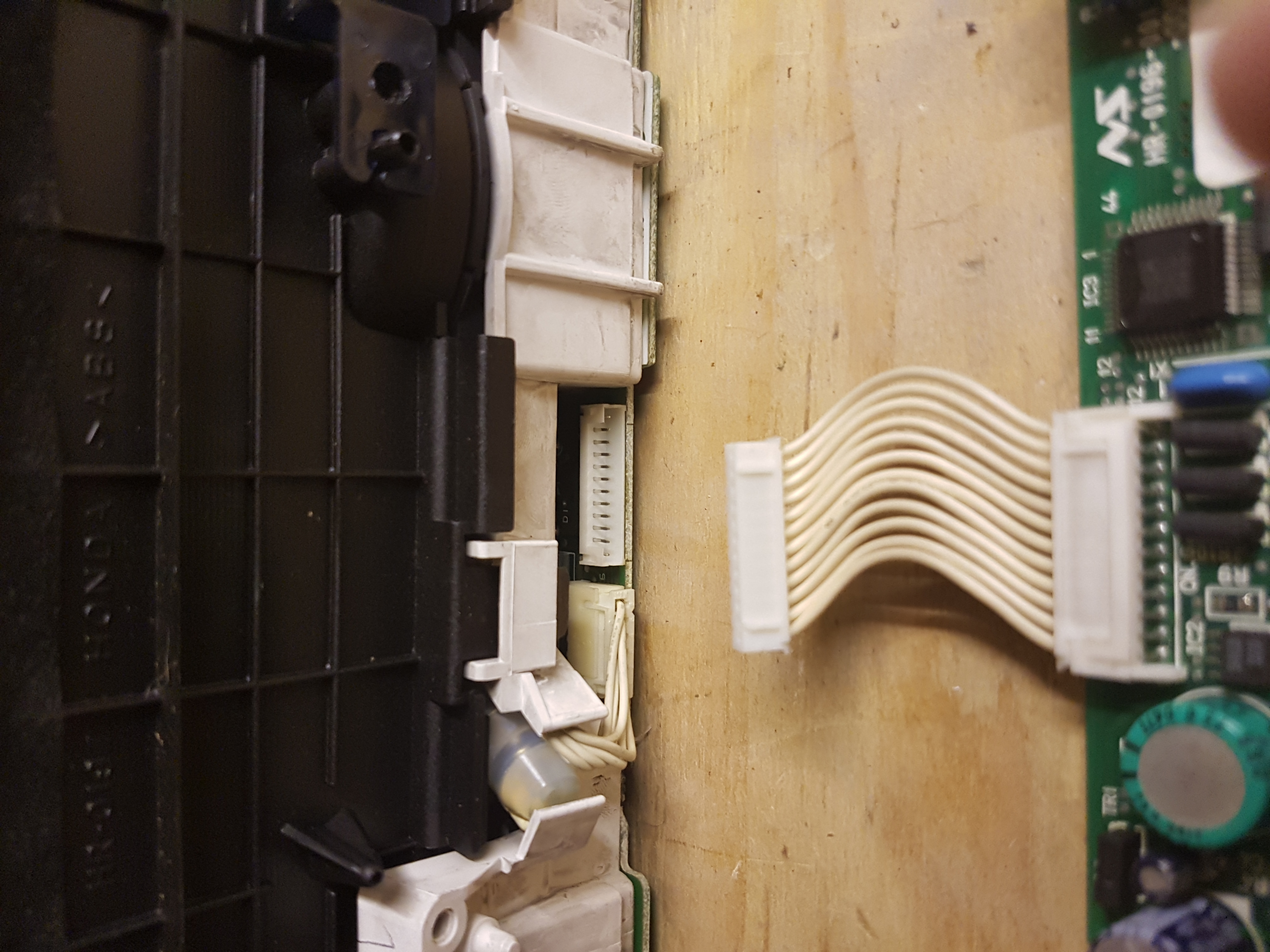
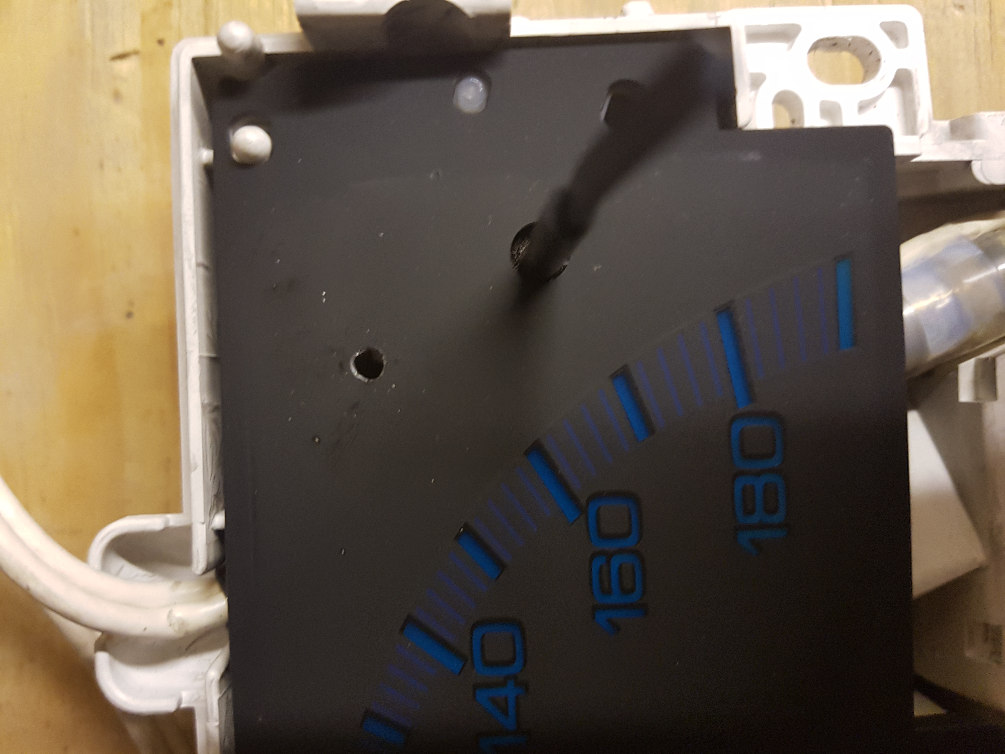
then you should be able to pop off the facia with a bit of gentle persuasion
try and remove straight off and try not to hit the needles
ALSO NOTE A WARNING DO NOT REMOVE THE NEEDLES
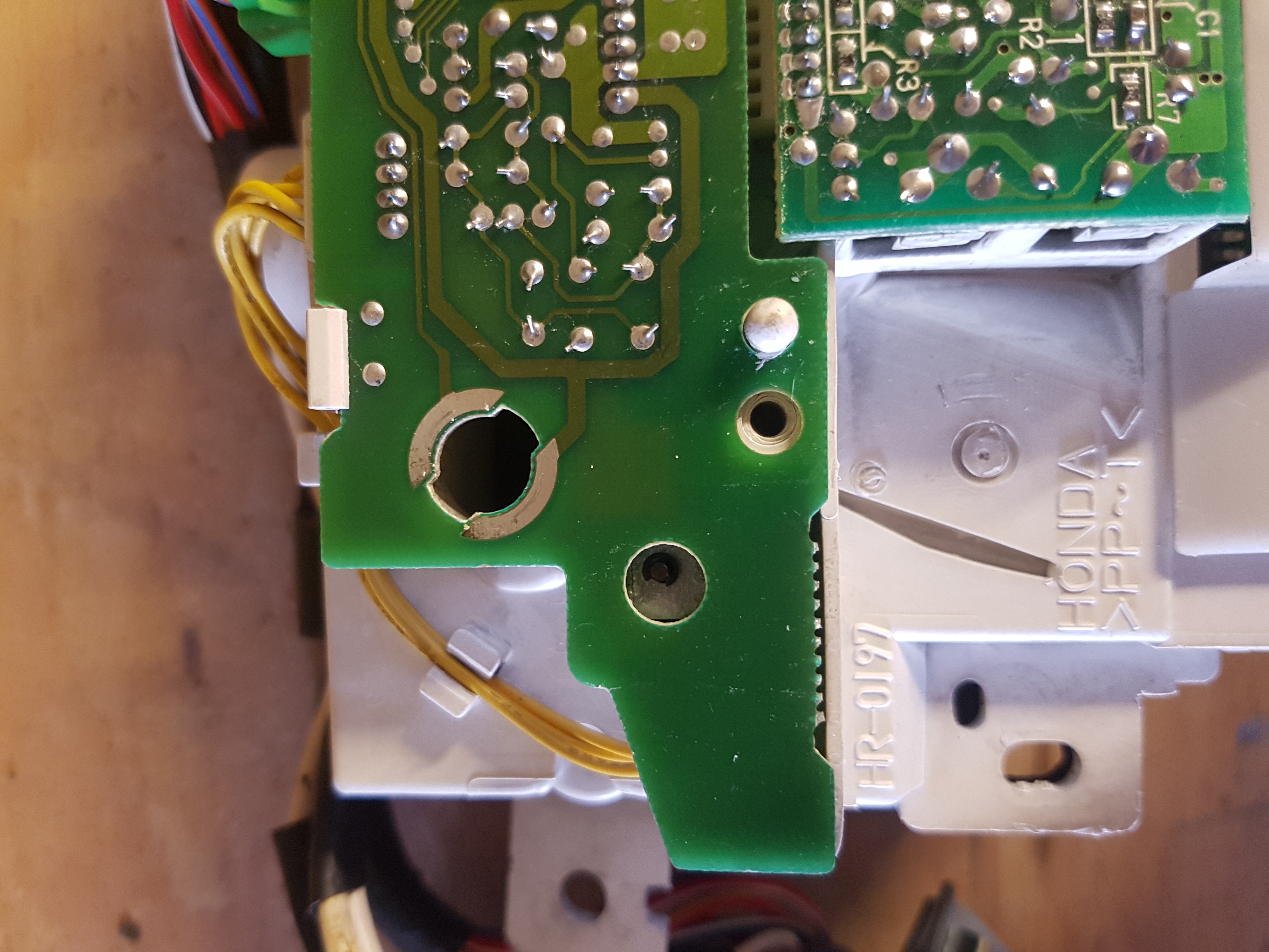
I then pulled the top right of the Dial facia gently and you will see that there is space for where the 4WS light should shine through. I made an educated guess and a 3mm drillbit to make a hole.
then carefully put all back together.
once done pop in a bulb from the old unit
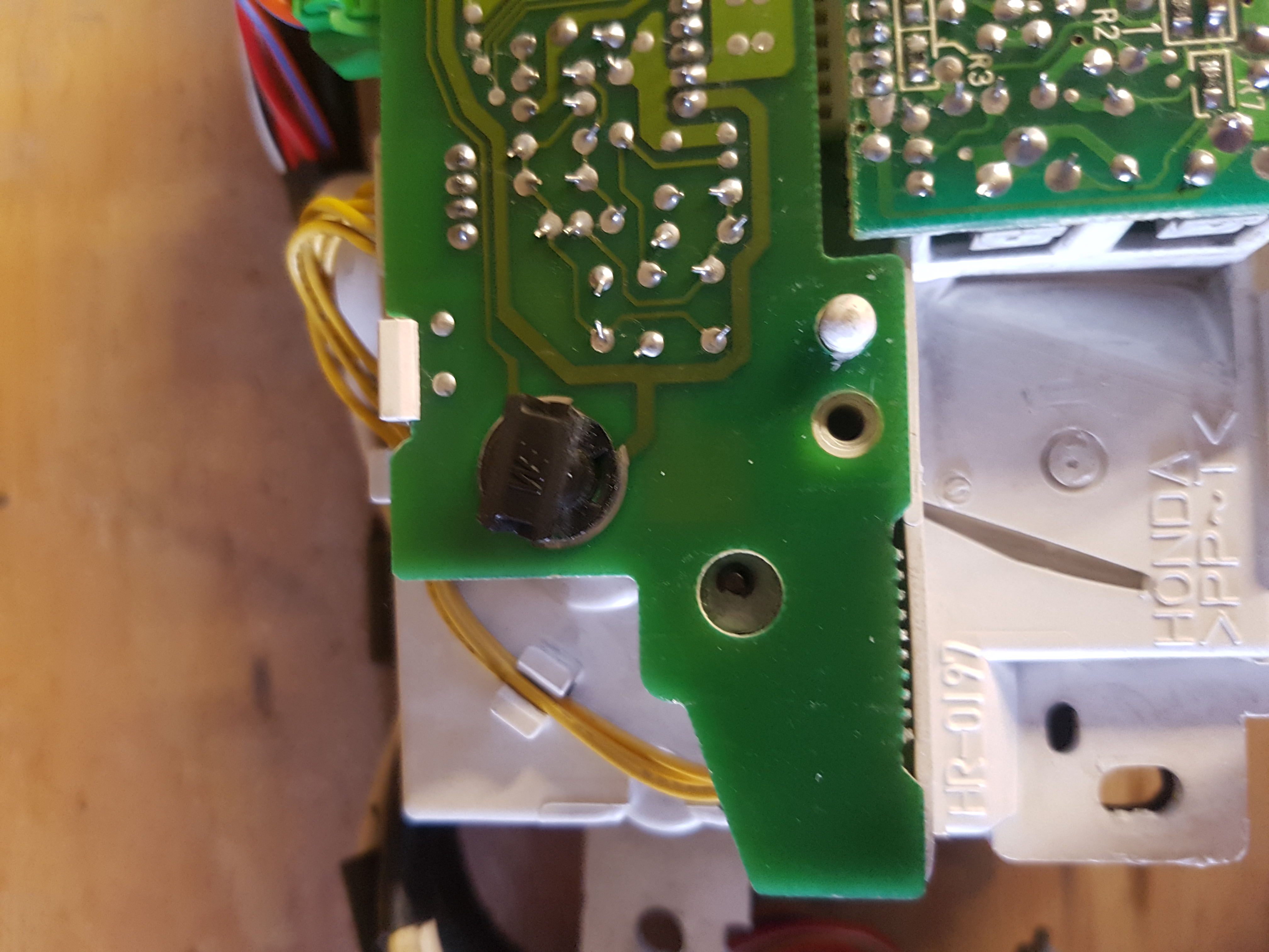
now when putting the metal plate back on you will see the bulb compromises this sitting correctly so i cut a bit off so the plate would sit flush
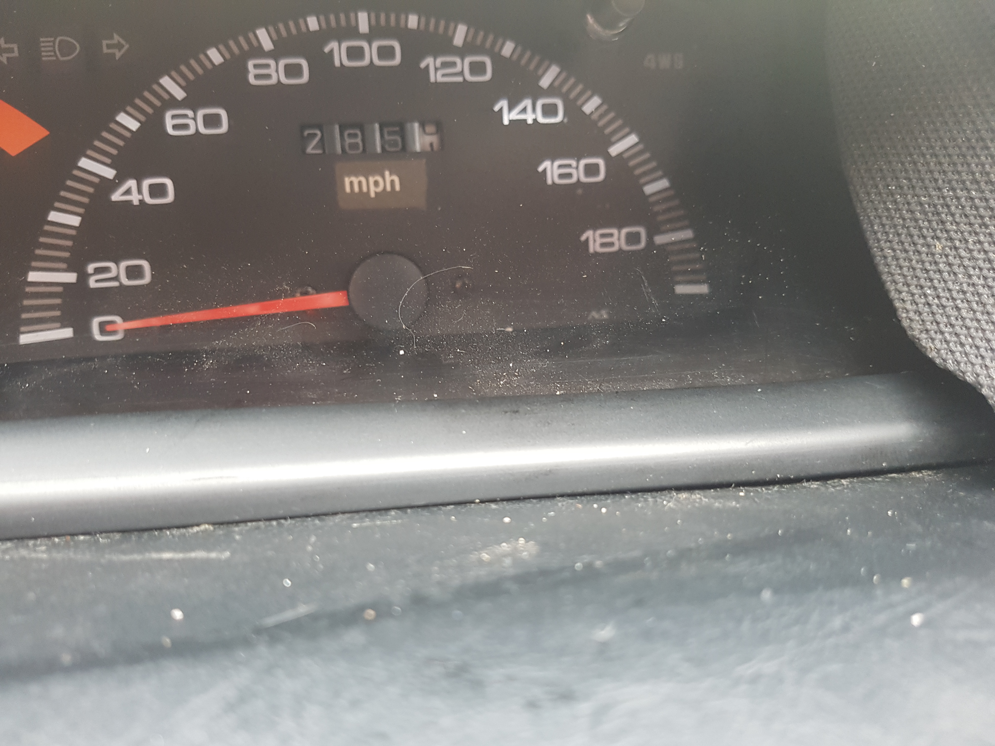
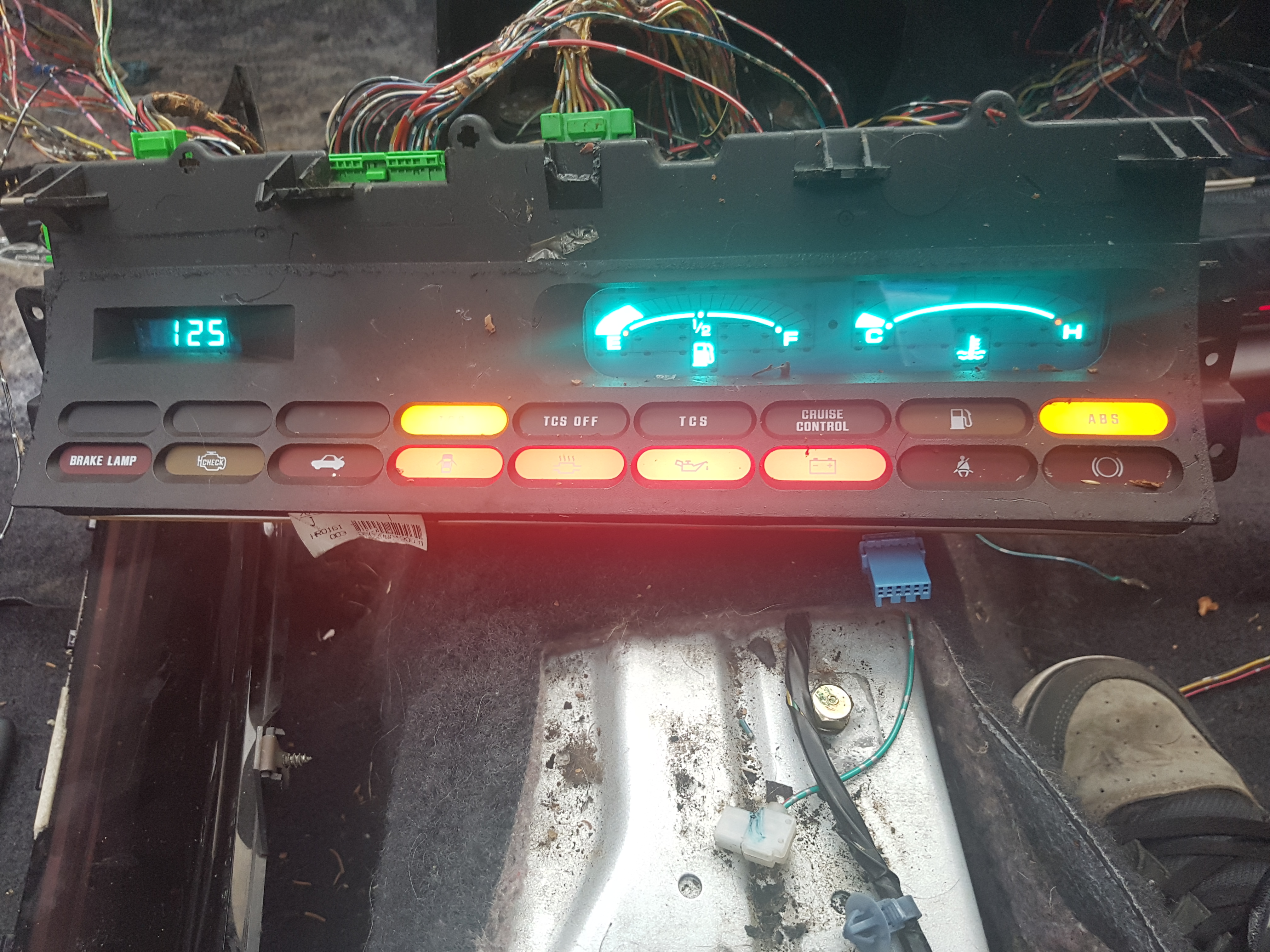
plugged all back in and this is what i get.
i then tidied up the loom
then reversed what i done to take the loom out the dials out then the facia's finished off with facelift tweeter covers:
FINAL OUTCOME
Now im not going to lie - this is picture heavy and the only reason for this was that i hope i can help someone and or many people if they wish to do this in the future. I may have missed out parts however i hope i didnt. If anyone has anything to add please tell me and i will do what i can to amend.
Anywho i know some/a few have done this and a few planning to do it...now i probably made more work for myself than needed but im happy in the knowledge it all works.
Now im not going to lie i used ammo post http://www.ludegeneration.co.uk/honda-p ... -t890.html for a lot of my help.
1st remove the tweeter covers (1st image ove 5mb)
pull off rubber seal at the bottom of the dash
then remove the 6 (i think) screws at the top of the dash
remove dash joint cover
Then remove the screws holding in the dials and the fuel/temp section should be 4 in each. Remove the plugs and set old dials to the side.
You should have it looking like this
Remove the white box also
Pull out the switches and remove the plugs
now in the driver footwell there are 3 plugs 2 grey 1 blue. Remove these.
then at the passenger footwell remove the glovebox number of screw in and around the glovebox
Remove the two grey plugs here also
then feed these up through the dash on both sides.
I came across the temp sensor on the dash. this is quite tricky and i removed the dash screws and and then use a screwdriver to pop through (be careful not to damage this) then remove the plug
Then it was probably a good thing the other half works nightshifts with the mess i made. As you might find the tape used is stickier than The Dead Marshes by Mordor. Use gloves or have wipes handy.
Both looms
Now the next part is purely a follow the colour and wire exercise. I removed all the loom tape from both however this wouldnt be needed.
1st i took the plug for the TCS and added it to the face lift loom
now the easiest thing to do is follow Ammos guide and switch over the wires needed.
I did not cut my wires i unplugged the wires from the plugs and put them in the facelift loom.
Pictures of how the plugs and wire colours should look:
Plug 1 bottom single row - temp & Fuel
Plug 2 top view - temp & fuel
Plug 2 bottom view - Temp & fuel
Plug 3 (shouldnt need any changes) - EL Dials
Plug 4 - EL Dials
Plug 5 top view - EL Dials
Plug 6 Top View - Driver footwell
Plug 6 Bottom View - Driver footwell
Plug 7 Top view - Driver footwell (short)
Plug 7 Bottom view - Driver footwell (short)
Plug 8 Top view - Driver footwell (long)
Plug 8 Bottom view - Driver footwell (long)
(also i forgot but move over the temp wires also)
there is a tracer wire that you will need to plug into the yellow splitter box. This was fun now the facelift splitter has smaller wire connectors than the pre facelift however with a little ingenuity i used this
held in place i plugged the splitter end of the plug back on and it held securely in place. Lots of electric tape.
Now you should be ready to test.
before you tidy up the loom plug into the footwells and make sure all is working.
You will have an extra earth wire this will need to be earthed to the car for the indicators and lights to work correctly.
Some troubleshooting was needed. My car does not have a dimmer as standard and as such i had issues with the dimmer box and plug.
this was how it all looked
all i done to rectify this was remove the dimmer box (im assuming because i dont have the dimmer switch attached it was causing an issue.
I them had life
well some...as you can see no EL speedo or rev lights (trust me at this point i was like what the god damn drokking son of a gun)
This was an easy fix and a mahoosive thank you to bennyboy it seemed i was missing a harness for the EL dials that connect to the inverter.
Bennyboy hooked me up with his spare harness and had it the next day so thank you so damn much mate.
plugged it in an voala
now before i could put all back together i had another issue. The 4WS warning light ... i shone a light through but nothing so i decided...lets dismantle and see what i can do...
On the back of the EL dials there is a metal plate remove this and you will see the space for the 4WS warning bulb
now be very careful and preferably on wooden bench or unit.
Remove the bottom white plastic
you will see two circuit boards
the one on the left not attached to anything
the one on the right has a small harness attaching to the dials remove this
then you should be able to pop off the facia with a bit of gentle persuasion
try and remove straight off and try not to hit the needles
ALSO NOTE A WARNING DO NOT REMOVE THE NEEDLES
I then pulled the top right of the Dial facia gently and you will see that there is space for where the 4WS light should shine through. I made an educated guess and a 3mm drillbit to make a hole.
then carefully put all back together.
once done pop in a bulb from the old unit
now when putting the metal plate back on you will see the bulb compromises this sitting correctly so i cut a bit off so the plate would sit flush
plugged all back in and this is what i get.
i then tidied up the loom
then reversed what i done to take the loom out the dials out then the facia's finished off with facelift tweeter covers:
FINAL OUTCOME
Now im not going to lie - this is picture heavy and the only reason for this was that i hope i can help someone and or many people if they wish to do this in the future. I may have missed out parts however i hope i didnt. If anyone has anything to add please tell me and i will do what i can to amend.
Last edited by sol-lude on Tue Oct 24, 2017 11:56 am, edited 3 times in total.