
so what goes to the sensor, 1x green and ...? as the sensors look like they need 2x wires going to them.
Congratulations to vtecmec for winning May/June's Lude Of The Month, with his DIY Turbo BB1 build.
>>> Click Here For Profile <<<

>>> Click Here For Profile <<<
Drax's JUN Prelude: Papa Smurf edition
-
Drax
- Moderator
- Posts: 6344
- Joined: Wed Dec 22, 2010 4:05 pm
- My Generation: 4G
- Location: Wrexham, North Wales
- Has thanked: 24 times
- Been thanked: 432 times
Re: Drax's JUN Prelude: H22 Papa Smurf edition
@njord @wurlycorner ignore what i supposedly corrected earlier, my notes were wrong so ive put right in the initial post what colour the wires are.....jesus im a dickhead 
so what goes to the sensor, 1x green and ...? as the sensors look like they need 2x wires going to them.
so what goes to the sensor, 1x green and ...? as the sensors look like they need 2x wires going to them.
2.2 JDM DOHC SI-VTEC LSD TCS 4WS ABS BB1 MANUAL 1992

FOR PAUL
FOR PAUL
-
wurlycorner

- Ye are glad to be dead, RIGHT?
- Posts: 21511
- Joined: Sat May 19, 2012 3:33 pm
- My Generation: 4G
- Location: Chelmsford, Essex
- Has thanked: 2507 times
- Been thanked: 317 times
I thought we were talking about the sensor on the IM?
Can you link back to the original post so we know which ones you're asking about for sure please?
(Unless it's just me being thick here and everyone else still knows what's going on...
General though:
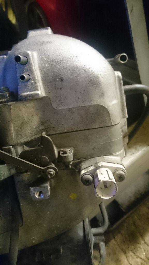
Oil pressure switches are normally just a single wire connection, positive feed from the pressure warning light, switch closes/opens to ground through the switch body and engine block. If it's a 2 wire sensor, it means instead of earthing to ground via the body, it has a return earth wire and goes to earth by that instead. It doesn't matter which wire is connected to which side.
Oil pressure sensors are the same, but instead of an on/off switch, they vary the resistance.
--
Iain.
Iain.
Super Secret 1G (not really super secret!)
-
Drax
- Moderator
- Posts: 6344
- Joined: Wed Dec 22, 2010 4:05 pm
- My Generation: 4G
- Location: Wrexham, North Wales
- Has thanked: 24 times
- Been thanked: 432 times
Re: Drax's JUN Prelude: H22 Papa Smurf edition
Sorry wurly, i havnt structured my questioning very well.
IAT Sensor
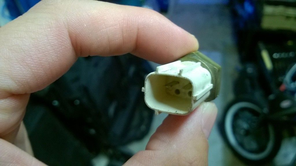
i just need to know which of the two wires are which, as both the ATR and Lude IAT use just two.
LUDE sensor
ATR sensor
---------------------------------------------------------------------------------------------------------------------------------
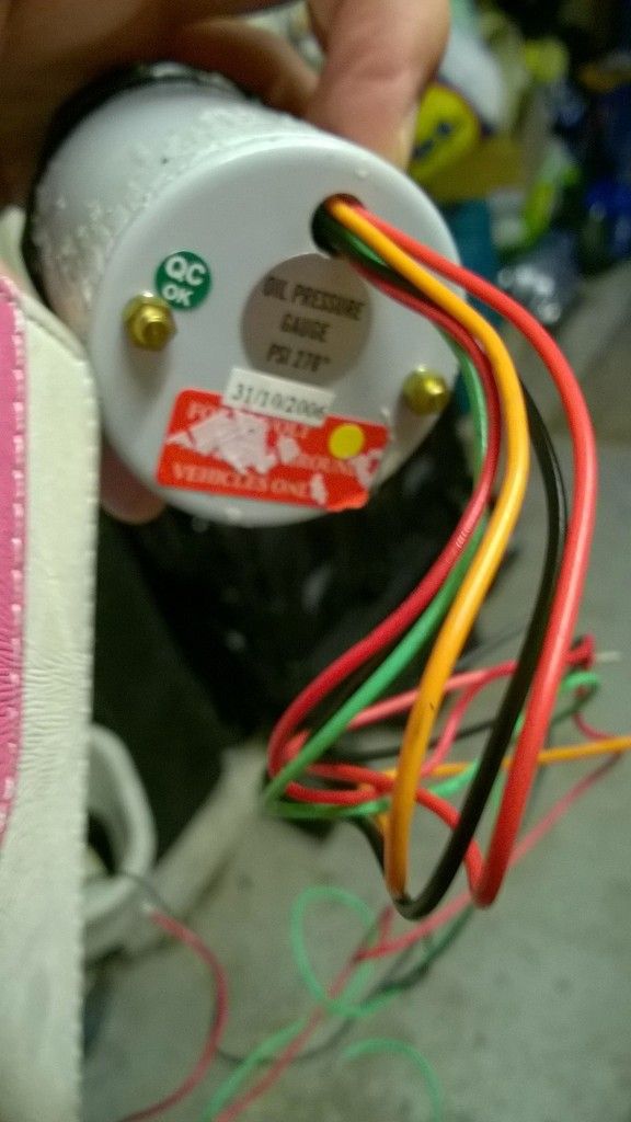
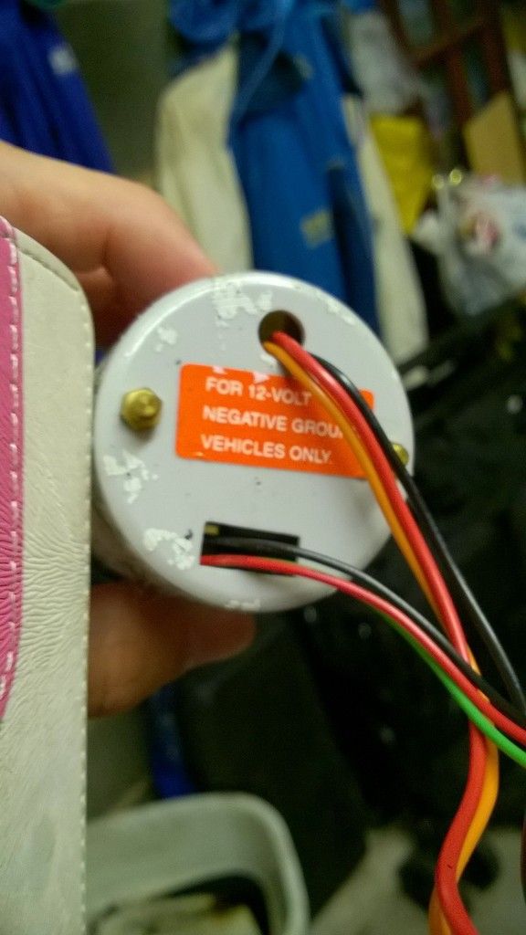
Oil Temp & Pressure gauge wiring
ive got my sensor in place for both of them, but i need to wire in the Gauges.
Research hasnt brought much up yet on how to wire them in, so;
they both have 6x wires - 3x thin red, black & GREEN wires, and 3x thicker red, black and ORANGE wires.
i can get pics up if required of both gauges and both sensor ends.
IAT Sensor
i just need to know which of the two wires are which, as both the ATR and Lude IAT use just two.
LUDE sensor
ATR sensor
---------------------------------------------------------------------------------------------------------------------------------
Oil Temp & Pressure gauge wiring
ive got my sensor in place for both of them, but i need to wire in the Gauges.
Research hasnt brought much up yet on how to wire them in, so;
they both have 6x wires - 3x thin red, black & GREEN wires, and 3x thicker red, black and ORANGE wires.
i can get pics up if required of both gauges and both sensor ends.
2.2 JDM DOHC SI-VTEC LSD TCS 4WS ABS BB1 MANUAL 1992
FOR PAUL
FOR PAUL
-
Drax
- Moderator
- Posts: 6344
- Joined: Wed Dec 22, 2010 4:05 pm
- My Generation: 4G
- Location: Wrexham, North Wales
- Has thanked: 24 times
- Been thanked: 432 times
Re: Drax's JUN Prelude: H22 Papa Smurf edition
will do!njord wrote:I think pics are needed as the ones ive got have 5 wires, one postive n ground for the back light, and then a positive, ground n sensor wire for the gauge
2.2 JDM DOHC SI-VTEC LSD TCS 4WS ABS BB1 MANUAL 1992
FOR PAUL
FOR PAUL
-
wurlycorner
- Ye are glad to be dead, RIGHT?
- Posts: 21511
- Joined: Sat May 19, 2012 3:33 pm
- My Generation: 4G
- Location: Chelmsford, Essex
- Has thanked: 2507 times
- Been thanked: 317 times
-
Drax
- Moderator
- Posts: 6344
- Joined: Wed Dec 22, 2010 4:05 pm
- My Generation: 4G
- Location: Wrexham, North Wales
- Has thanked: 24 times
- Been thanked: 432 times
Re: Drax's JUN Prelude: H22 Papa Smurf edition
wurlycorner wrote:IAT will just be a thermister (varies resistance dependant on temp) so it doesn't matter which way round you put the two wires on.
2.2 JDM DOHC SI-VTEC LSD TCS 4WS ABS BB1 MANUAL 1992
FOR PAUL
FOR PAUL
-
Drax
- Moderator
- Posts: 6344
- Joined: Wed Dec 22, 2010 4:05 pm
- My Generation: 4G
- Location: Wrexham, North Wales
- Has thanked: 24 times
- Been thanked: 432 times
Re: Drax's JUN Prelude: H22 Papa Smurf edition
Oil Pressure Gauge
Oil Temp Gauge
Wiring Diagram (just found!)
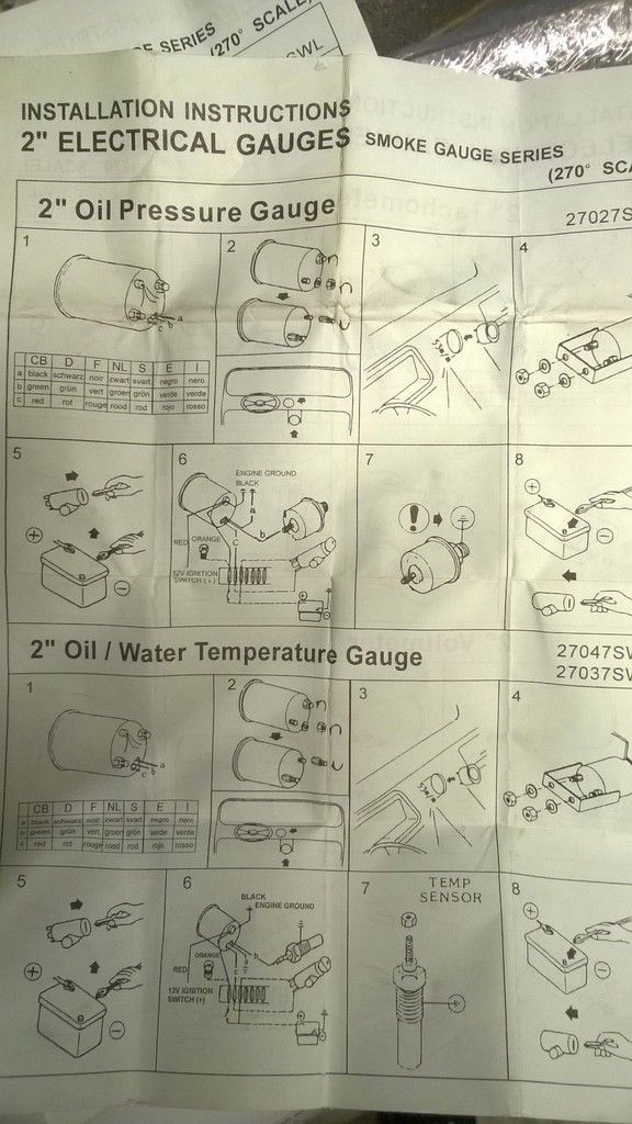
so, from the diagram im not sure where "C" and "Orange" go for Oil Pressure?
and the same again for the Oil Temp, but is "A" this time an Earth going somewhere else?
Oil Temp Gauge
Wiring Diagram (just found!)
so, from the diagram im not sure where "C" and "Orange" go for Oil Pressure?
and the same again for the Oil Temp, but is "A" this time an Earth going somewhere else?
2.2 JDM DOHC SI-VTEC LSD TCS 4WS ABS BB1 MANUAL 1992
FOR PAUL
FOR PAUL
-
wurlycorner
- Ye are glad to be dead, RIGHT?
- Posts: 21511
- Joined: Sat May 19, 2012 3:33 pm
- My Generation: 4G
- Location: Chelmsford, Essex
- Has thanked: 2507 times
- Been thanked: 317 times
But...
For Oil presssure I would say that Orange needs to connect to the existing oil pressure switch wire - that's the one that will put the oil pressure warning light on on the dashboard.
C looks like it wants to be a switched ignition live.
And for the oil temp gauge, yes it looks like A needs to be connected to earth.
--
Iain.
Iain.
Super Secret 1G (not really super secret!)
-
Drax
- Moderator
- Posts: 6344
- Joined: Wed Dec 22, 2010 4:05 pm
- My Generation: 4G
- Location: Wrexham, North Wales
- Has thanked: 24 times
- Been thanked: 432 times
Re: Drax's JUN Prelude: H22 Papa Smurf edition
cheers Wurly, much appreciated  ill give this wiring a go asap.
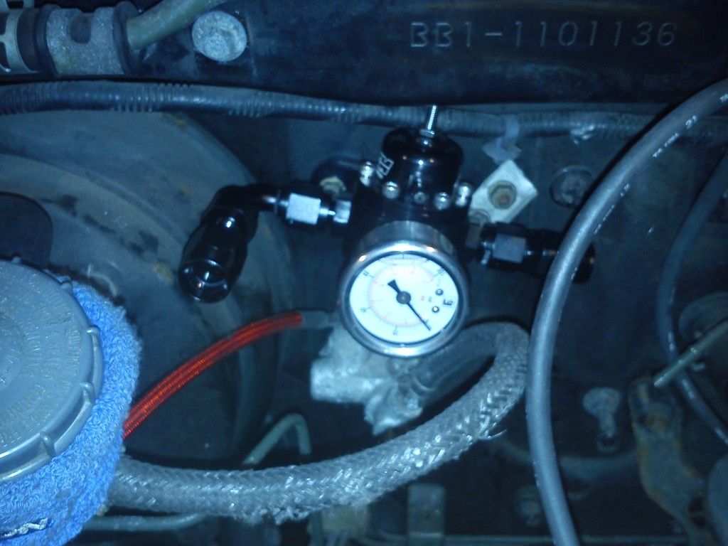
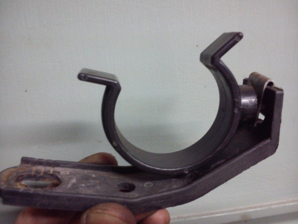
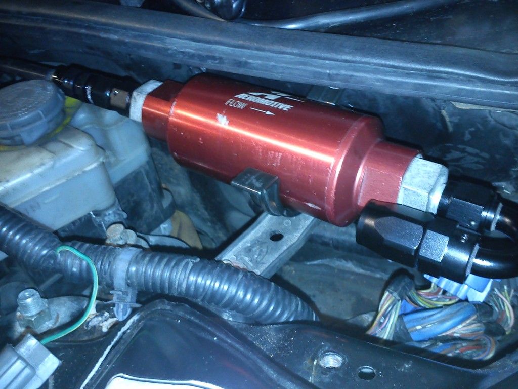
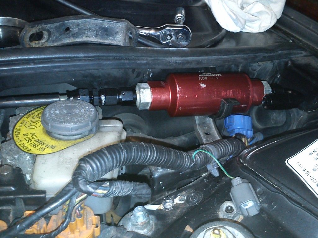
quick update in the meantime, some of the fueling ive manage to sort out.
AN fittings on the fuel rail
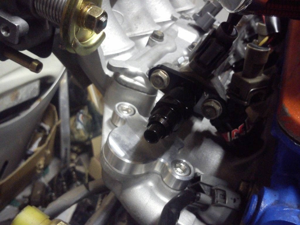
AEM FPR with a home made bracket to fit to the rear left of the firewall
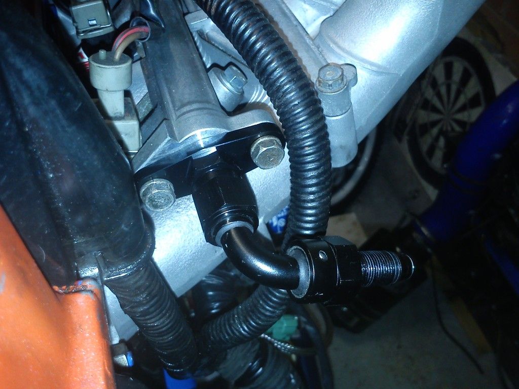
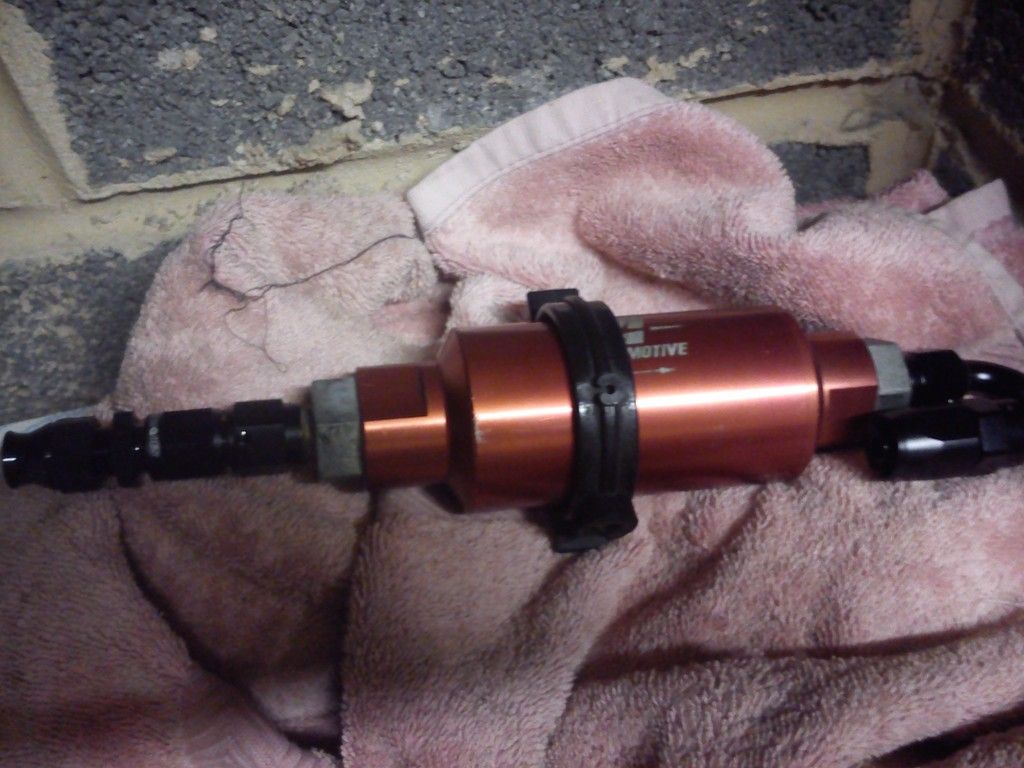
AN fittings on the replacement fuel filter (double danny's old one)
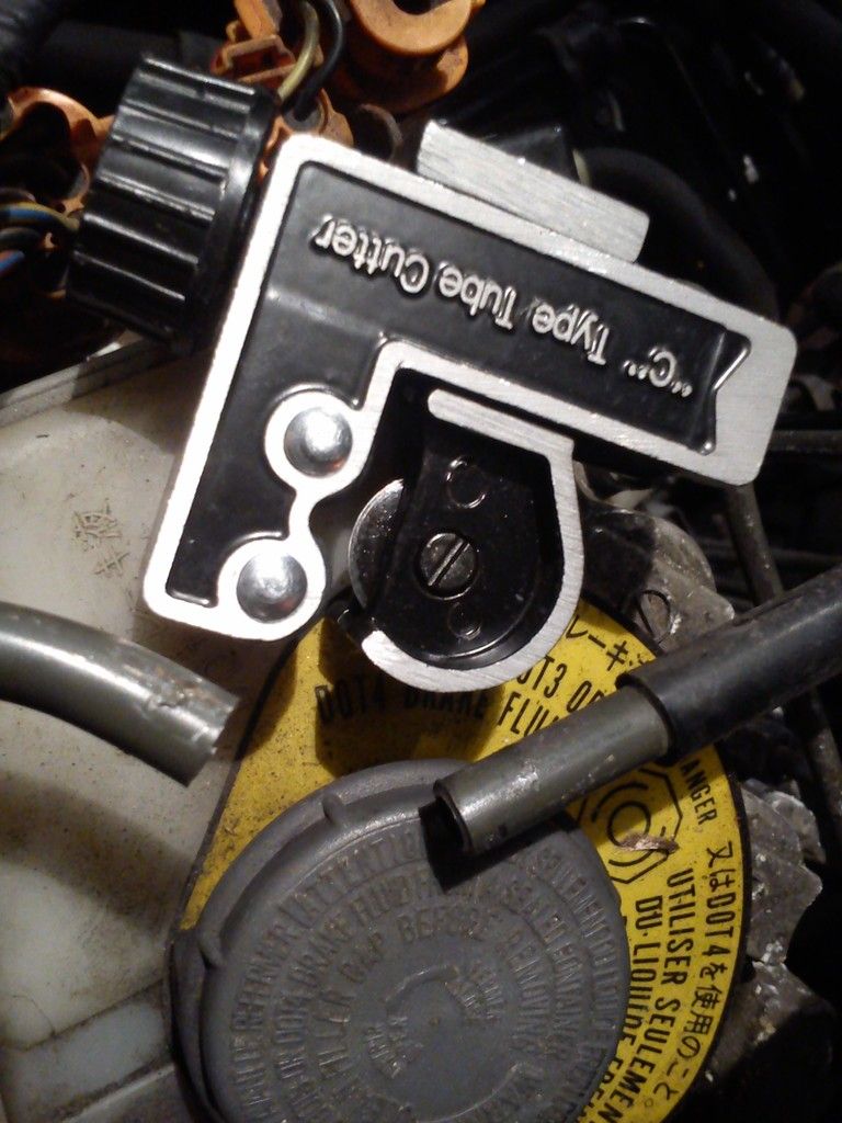
needed to cut the fuel line in to fit this, so bought the screwfix cheap pipe cutter as advised...snip!
and AN fitting put on
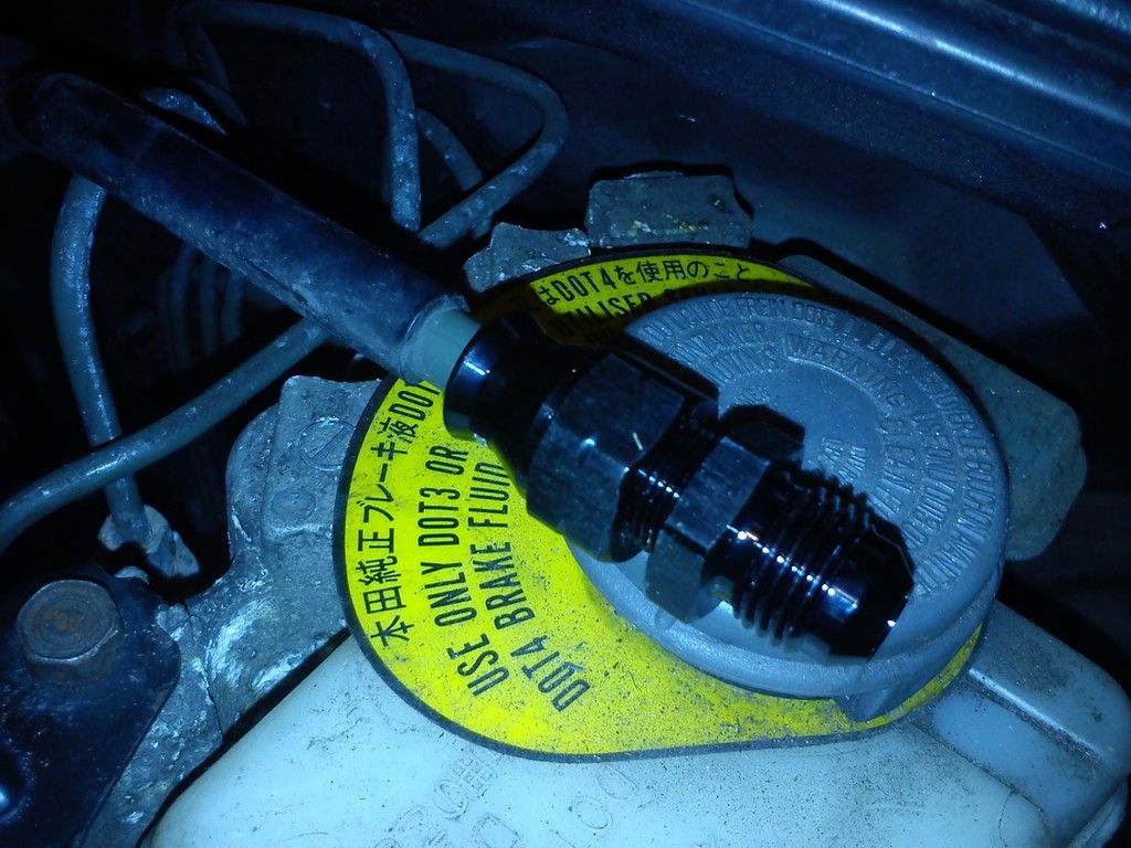
home made backet to hold the fuel filter in place
and both fitted...like a glove!
the oil cooler is now fitted too, will get pics of that asap.
quick update in the meantime, some of the fueling ive manage to sort out.
AN fittings on the fuel rail
AEM FPR with a home made bracket to fit to the rear left of the firewall
AN fittings on the replacement fuel filter (double danny's old one)
needed to cut the fuel line in to fit this, so bought the screwfix cheap pipe cutter as advised...snip!
and AN fitting put on
home made backet to hold the fuel filter in place
and both fitted...like a glove!
the oil cooler is now fitted too, will get pics of that asap.
2.2 JDM DOHC SI-VTEC LSD TCS 4WS ABS BB1 MANUAL 1992
FOR PAUL
FOR PAUL