
I've obtained a pair of turn illumination lights, but no loom. I guess there's a control box for these?
I don't have that so I'd like to make one. But I can't find in the manual anything about these lights, does anyone have any info? i.e. where the conrol box lives, how it connects etc?
Also, while the bumper is off I'm gonna fit fog lights. Someone linked to the dealer guide on here on how to fit these but I can't find that now - could someone remind me please?
Ta
A
Congratulations to vtecmec for winning May/June's Lude Of The Month, with his DIY Turbo BB1 build.
>>> Click Here For Profile <<<

>>> Click Here For Profile <<<
Turn lights installed!
Turn lights installed!
Last edited by alinton on Sun Sep 27, 2015 7:59 pm, edited 1 time in total.
---------------------
'96 BB4.
'96 BB4.
-
Merlin

- Moderator
- Posts: 12397
- Joined: Fri Aug 06, 2010 9:04 am
- My Generation: 5G
- PSN GamerTag: Merlinbadman
- Location: Edinburgh
- Has thanked: 71 times
- Been thanked: 306 times
I think this is the thread you were looking for http://www.ludegeneration.co.uk/electri ... 15998.html

-
vanzep
- Supporter 2016
- Posts: 7178
- Joined: Sun Jan 29, 2012 6:38 pm
- My Generation: 4G
- Location: Edinburgh
- Has thanked: 314 times
- Been thanked: 526 times
im surprised you didnt get the control box with the turn lights as the seller had it up for sale at the same time 
1996-2000 1993 EG9 Blue Civic 1.6 Vti - Traded in against the BB4
2000-2019 1994 2WS BB4 Milano Red JDM Prelude Si VTEC LSD
2015 on > 1991 4WS BB1 Phantom Pearl Grey JDM Prelude Si VTEC LSD
2021 ON > 1998 2WS BB6 White Pearl JDM Prelude Si VTEC
2000-2019 1994 2WS BB4 Milano Red JDM Prelude Si VTEC LSD
2015 on > 1991 4WS BB1 Phantom Pearl Grey JDM Prelude Si VTEC LSD
2021 ON > 1998 2WS BB6 White Pearl JDM Prelude Si VTEC
-
jjmartin349571
- Supporter 2016
- Posts: 3344
- Joined: Fri Feb 10, 2012 12:41 am
- My Generation: 4G
- XBOX GamerTag: jjm349571
- Location: Newhaven, East Sussex
- Contact:
I imagine the control box is just a timer circuit taking a signal from the indicators. Probably could be reproduced at home with readily available components.
edit:
A pair of these might do the trick - I'd use a relay as the input (instead of the push to make switch), wired in series to the relevant indicator for the signal. Then have the corner/turning light as the output.
Someone more electrically minded may want to confirm or add to that though, as that link is the first one that popped up from a quick google at work...
I didn't know he had the box!
I've already built a little circuit that will work. You don't need a 555, just a resistor, capacitor and transistor.
The indicator 'on' pulse switches on the transistor which fires the relay, whilst charging the capacitor. when the pulse disappears the capacitor slowly discharges via the resistor, as the voltage decays the transistor stays on for a while, thus keeping the relay on and the lights lit. After the cap has discharged the transistor switches off and the relay drops out. My circuit extends the indicator pulse by about 1.5 secs, which is more than enough for the next pulse to come along.
I'll post pic of the circuit and the new control box when I've finished it.
Obviously it'd have been easier if I had the original box!
And re the fogs, I've got all the parts now, bezels courtesy of Vanzep and the button from a Lithuanian boy I came upon not far from me who's dissembled four ludes and is building one good one from the bodyshell up!
A.
---------------------
'96 BB4.
'96 BB4.
Halfway through this job now. Fogs fitted.
Re the intersection (turn) lights, anyone know exactly where the control box lives? I've made one, it works, but not sure where to put it.
Here's my controller for the intersection lights:
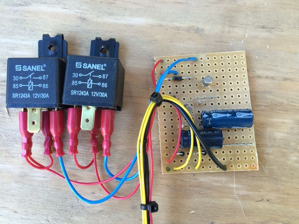
The empty relay connections go to the lamps. The yellows are from the indicators, black is -ve and red is from the sidelights. Obviously it's a 2-channel circuit, left and right.
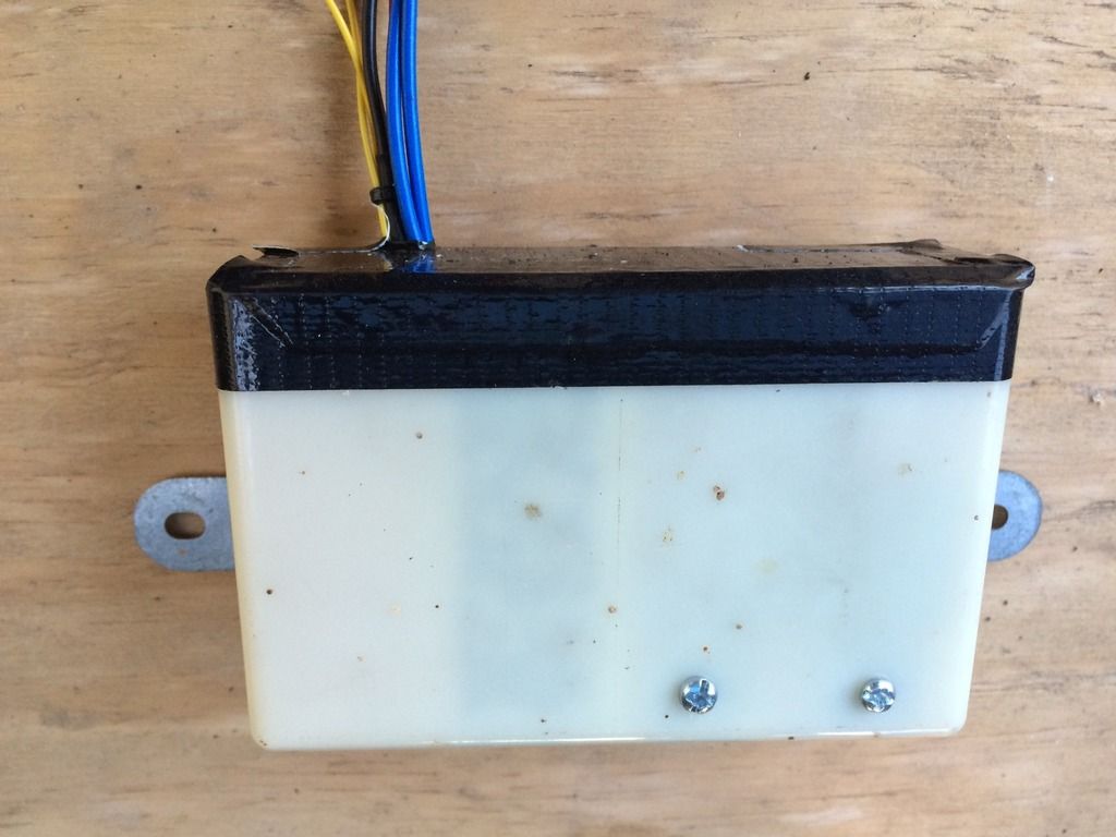
And here it is in a box. You might recognise the box. It's from a Lude, but I'm not sure what it used to be!
A.
Re the intersection (turn) lights, anyone know exactly where the control box lives? I've made one, it works, but not sure where to put it.
Here's my controller for the intersection lights:
The empty relay connections go to the lamps. The yellows are from the indicators, black is -ve and red is from the sidelights. Obviously it's a 2-channel circuit, left and right.
And here it is in a box. You might recognise the box. It's from a Lude, but I'm not sure what it used to be!
A.
---------------------
'96 BB4.
'96 BB4.
-
wurlycorner

- Ye are glad to be dead, RIGHT?
- Posts: 21511
- Joined: Sat May 19, 2012 3:33 pm
- My Generation: 4G
- Location: Chelmsford, Essex
- Has thanked: 2507 times
- Been thanked: 317 times
Well done knocking that up. Was either a folding mirror or auto power window relay box.
The oem controller is a potted unit and lives on the front of the centre upright, in front of the rad. As that isn't potted, I certainly wouldn't recommend putting it there - bit too exposed!
The oem controller is a potted unit and lives on the front of the centre upright, in front of the rad. As that isn't potted, I certainly wouldn't recommend putting it there - bit too exposed!
--
Iain.
Iain.
Super Secret 1G (not really super secret!)
Ha that does seem to be a precarious location! I'll try hide mine somewhere else. Or I'll pour some potting compound into it!
Here's the circuit diagram - one channel only shown. Easy to knock up on a bit of veroboard.
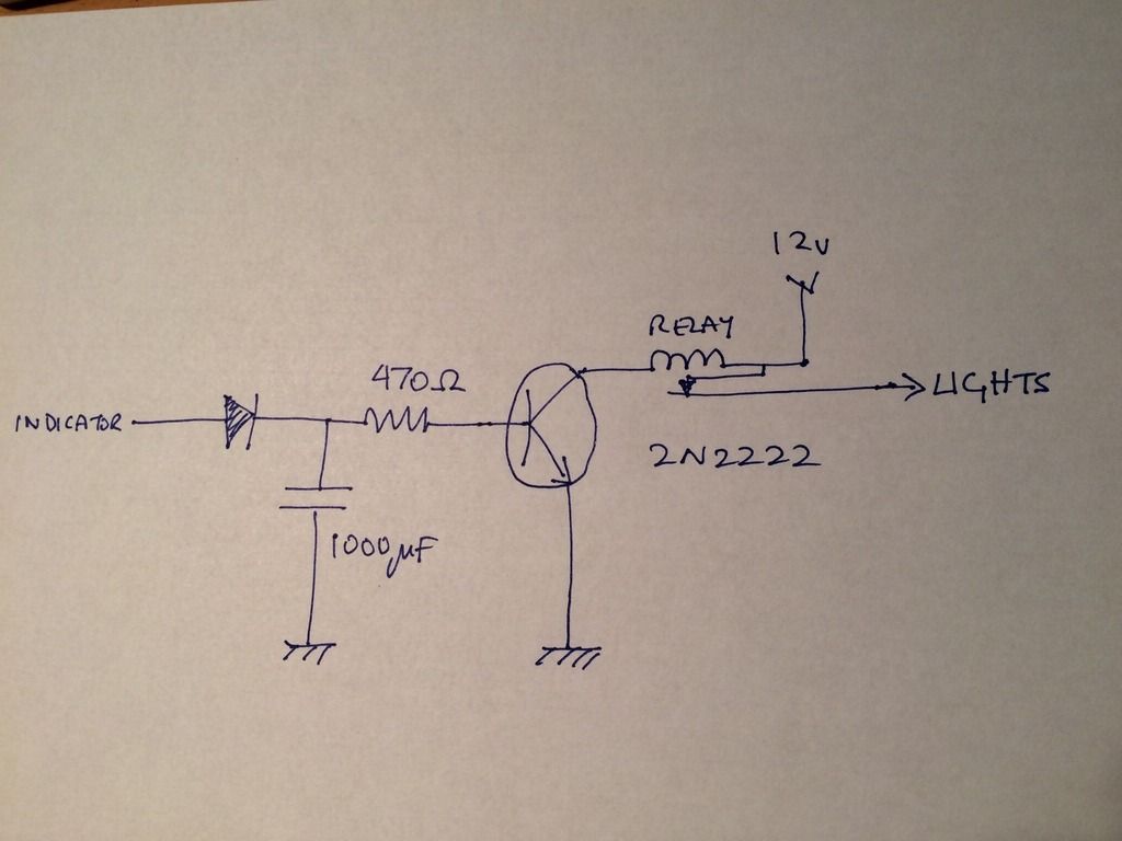
I forgot to show a reverse polarity diode across the relay, to protect the transistor from the back-emf. The first diode (both are 1N4001 - cheap as chips) is to prevent the capacitor from discharging through the indicator circuit that feeds it.
I'd actually love to see the circuit of the proper control box - no chance of that I'd say if it's potted.
Here's the circuit diagram - one channel only shown. Easy to knock up on a bit of veroboard.
I forgot to show a reverse polarity diode across the relay, to protect the transistor from the back-emf. The first diode (both are 1N4001 - cheap as chips) is to prevent the capacitor from discharging through the indicator circuit that feeds it.
I'd actually love to see the circuit of the proper control box - no chance of that I'd say if it's potted.
---------------------
'96 BB4.
'96 BB4.
Spent today with the front of the car off, fitting fog lights and the intersection lights.
I decided not to use the box in the post above, so instead I put my little circuit board in a smaller box and mounted it behind the front panel, kinda behind the Honda badge, and I mounted the relays that switch on the lights near them, one on each side - here's the drivers side, next to the void where the resonator was:
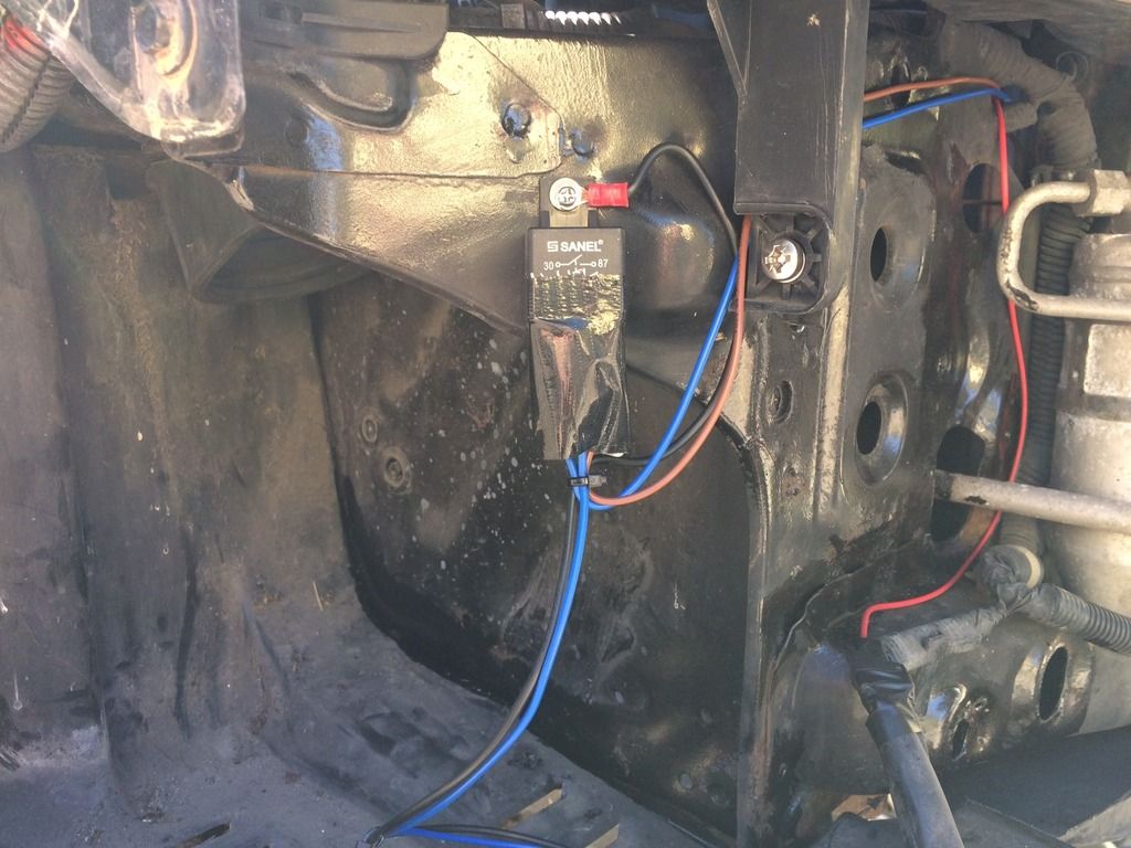
The near side one is in a similar position next to the washer bottle. Notice the home-made shroud protecting the contacts from moisture - no point in trying to seal it completely, it's better to just shroud the contacts but leave the bottom open so any moisture that does end up there will drain out.
I picked up the supply for the control circuit from the sidelight wire in front of the air filter, and tapped into the indicator wires just where they leave the flexible conduit. Soldered, not Scotchloked! That's the red wire in the pic.
Here's a little vid of the result:
http://youtu.be/EV2jPs05kaE
I fitted the fog lights today too, but they won't work until I fit the relay inside (although when I looked I couldn't find the plug for it!) and I don't have the switch for them yet either.
A.
I decided not to use the box in the post above, so instead I put my little circuit board in a smaller box and mounted it behind the front panel, kinda behind the Honda badge, and I mounted the relays that switch on the lights near them, one on each side - here's the drivers side, next to the void where the resonator was:
The near side one is in a similar position next to the washer bottle. Notice the home-made shroud protecting the contacts from moisture - no point in trying to seal it completely, it's better to just shroud the contacts but leave the bottom open so any moisture that does end up there will drain out.
I picked up the supply for the control circuit from the sidelight wire in front of the air filter, and tapped into the indicator wires just where they leave the flexible conduit. Soldered, not Scotchloked! That's the red wire in the pic.
Here's a little vid of the result:
http://youtu.be/EV2jPs05kaE
I fitted the fog lights today too, but they won't work until I fit the relay inside (although when I looked I couldn't find the plug for it!) and I don't have the switch for them yet either.
A.
---------------------
'96 BB4.
'96 BB4.