Congratulations to vtecmec for winning May/June's Lude Of The Month, with his DIY Turbo BB1 build.

>>> Click Here For Profile <<<

Image

Never Ending Story... Prelude race car build.

Tell us all about your Lude, you know you want to ...
User avatar
Buzzonion Vtec
Posts: 214
Joined: Sat Jan 28, 2012 10:29 am
My Generation: 4G

Re: Thread Building - Please don't reply just yet ;-)

Post by Buzzonion Vtec » Sun Jan 29, 2012 9:27 pm

REPLY


Before I get on with some long overdue updates :oops:

Jezer
The advantages for running COP are reliability, spark power and controlability of individual cylinder spark patterns if required.
Whether or not it's worse for a single coil to fail or a whole dizzy obviously depends on your standpoint. If the dizzy fails, that's it, game over. If a single coil fails teh engine will continue to run but will obviously just have a single cylinder out which means that you could finish the race rather than retire.

njord
Yep that's another way of ditching the dizzy but you obviously still need to run HT leads. Wasted spark tends not to be as powerful either but still better than a single coil dizzy.


Rich

User avatar
Buzzonion Vtec
Posts: 214
Joined: Sat Jan 28, 2012 10:29 am
My Generation: 4G

Build Up 6 - Brake system

Post by Buzzonion Vtec » Sun Jan 29, 2012 9:28 pm

Update 16 – Originally Posted - Mon Aug 30, 2010 6:02 pm

http://preludeuk.forumup.com/viewtopic. ... =preludeuk


Right then...update time :D
All usual excuses for the delays are in place - lack of time, work commitments etc etc etc but as usual the progress has not been rushed and there are still some parts of the following updates that are not 100% complete or that I'm 100% happy with. Some of unfinished bits are due to decisions on items like dash display systems or wiring loom work still needing to be done to finish things off.

I think I'll tackle these updates in stages as there is a bit to get through.

First on the list...

Brakes

So my Prelude was the very first to be blessed with the Hi-Spec 325x30mm "monster 4" conversion way back in the day. Hi-Spec used the car to develop the kit that then went on sale. Having been faultless over the many years that I have used them I decided they would stay although I did swap over to the black calipers rather than the gold ones I originally had on the car.
The rest of the braking system had remained pretty much standard but I always felt the rear was being overworked so during this part of the build as everything had already been removed I decided to take the opportunity to upgrade everything else in my usual single minded oddball way :D


Rear brake upgrade - Standard 262mm on right, 302mm Mondeo 2.5lt (07 on) disc on left. This was selected not just because of it's size (which met my requirements) but also because the offset was pretty close to exactly the offset I'd worked out that I needed. It took some research but it was worth it ...especially when I discovered how cheap they were :lol:

Image


Comparing the sizes - bigger discs is also 2mm thicker which is great for the ability to deal with heat

Image


Mondeo disc drilled for 4x114.3 Prelude PCD

Image


The original rear brake caliper mounting method has the M10 bolts passing through the hub and screwing into the caliper carrier, this will still the case but for the new caliper mounting bracket the rear hub was drilled out and taped to M12 to allow for caliper mount bracket fitting.

Image


Alloy plate to make caliper relocation mounts - OEM Prelude calipers to be used (initially)

Image


Caliper mount cut out from alloy plate and profiled to clear hub

Image


Caliper mount bolted into place. You can now see the need for the drilling and tapping of the hub, bear in mind that the bracket is moving the caliper inboard to match the increased offset of the disc

Image


OEM Prelude caliper carrier needed a small amount of trimming and clearancing for good fit against alloy bracket.

Image


302mm disc, caliper mount and caliper carrier in place.

Image


Rear view of carrier bolted to alloy mount. Pads were installed during marking out to help with optimum carrier positioning.

Image


Another view showing pads making the most of the available disc diameter

Image


More shaping of the alloy mount was required to allow for the actual caliper to bolt into place. It was pretty much just the piston housing are that caused the problem as can be seen from the following pics.

Image

Image

Image


So with the main fabrication and setup work done I could now complete the fitting and centralising of the setup.
Mount shown here with the two shims required to perfect the central mounting of the caliper over the disc

Image


Fully assembled 302mm rear brake upgrade with OEM Prelude caliper

Image

Image


Stock disc vs 302mm upgrade behind 17in wheels for comparison

Image

Image


With the mocking up and trial fitment work all done I could now carry out the swap over to an Integra DC5 alloy caliper. These are lighter and better for cooling than the OEM Prelude caliper. I'd already found that these are as near as damn it a direct swap (using n/s/r DC5 on o/s/r of Prelude) so it would simply be a case of bolting them into place. BTW I am sticking with the OEM Prelude carriers as these are lighter than the DC5 items and also the DC5 carriers are slightly different spacing.

Image

Image


A quick weigh in of the two calipers just for reference

Image

Image


Before bolting the DC5 item into place

Image

Image

Image


Time to remove everything again as I didn't like the look of the "go faster" red caliper colour...especially against the Orange body colour.
Decided to compare the weights of the complete OEM setup vs the complete conversion setup and was happy to see that the lighter weight of the alloy caliper has offset the increased disc weight so the bigger discs conversion comes in at near as damn it the same same weight as OEM. Result 8)

So with a quick tidy up of the conversion and a bit of nifty paintwork I ended up with this...the finished article.

Image

Image

Image

Image


Well, I say finished. Next I had to install the handbrake cables as a quick test fit to make sure the relocation of the calipers had not caused too much of an issue with cable fitment. It hadn't as you can see

Image


However, I didn't like how untidy it all looked and add to that the weight of the cables...I was about to have a change of mind...more of that in a bit though :wink:


Before going any further I decided to freshen up the Hi Spec front end setup. As a reminder, this is the 325x30mm conversion using the "Monster4" caliper. Plenty big enough for what I need and have always been super reliable so no reason to change.

Image

Image

Image


Now all of the main hardware was in place it was then just the small matter of linking them all up with new brake lines. I toyed with the idea of making up and running full braided lines everywhere but discounted that due to the fact that the chosen brake pipe material is both lighter and stronger. I have selected a copper/nickle brake pipe for it's combination of strength (TUV and FIA approval), durability and lightweight. I have kept the pipe runs as short and neat as tidy as possible. The final flexi hoses used are supplied by HEL.
Note - brake circuits to be split front/rear rather than the OEM diagonal split.

Image

Image

Image

Image


Rear line passing through the bulkhead via a dedicated fitting into the car

Image


Leading to the Wilwood adjustable brake bias valve. This will obviously enable me to optimise the rear braking efficiency and change the balance in different conditions.

Image


From out of the bias valve the brake line then continues into the hydraulic handbrake. I decided to go down this route rather than run the OEM item and cables in the simply because this is lighter and much tidier. It also allowed me to rid the calipers of the handbrake brackets which saved bit more weight. Note the mechanical locking device which is folded out at the moment. The handbrake is basically a fly off type (meaning no button) so this device is what locks it on.

Image


From out of the handbrake, through the floor and split across to both rear brakes via the lightened rear flexi hose mounting bracket

Image

Image

Image

Image

Image


With all the brake components fully linked up all that was left to do was to fully bleed the system and test it for operation and leaks. That done it was at last another job fully ticked off the very long list.

:D
Last edited by Buzzonion Vtec on Sun Jan 29, 2012 10:53 pm, edited 1 time in total.

User avatar
Buzzonion Vtec
Posts: 214
Joined: Sat Jan 28, 2012 10:29 am
My Generation: 4G

Re: Thread Building - Please don't reply just yet ;-)

Post by Buzzonion Vtec » Sun Jan 29, 2012 9:29 pm

REPLYS

Ammo wrote:What did you do to the Monster 4 calipers? Mine need a refurb as they are currently in there original anodised state and look horrible :(

lewd lude lover wrote:^^^sell them to me ammo!!!


my word rich, respect builds as fast as this car. i really cant wait to come to the first outing on track.
Nafeman wrote:Stop giving me ideas!!! :lol:
.

User avatar
Buzzonion Vtec
Posts: 214
Joined: Sat Jan 28, 2012 10:29 am
My Generation: 4G

Build Up 7 - Single wiper conversion

Post by Buzzonion Vtec » Sun Jan 29, 2012 9:29 pm

Update 17 – Originally Posted - Mon Aug 30, 2010 7:07 pm

http://preludeuk.forumup.com/viewtopic. ... =preludeuk


Update continued

Onto the single wiper conversion now.
I decided to take a look at how much weight could be saved from the wipers and wiper motor/linkage and thought the simplest solution was to go down the single wiper conversion route. What I wanted though was for the single wiper to sweep the full screen so rather than just deleting the n/s wiper arm I got on with modifying the linkage to delete the o/s wiper (drivers side) and use the n/s wiper spindle with an extended sweep pattern.
Here's how it is done. I have included all the info as best I can so if you want to perform the conversion yourself you can.


Complete original wiper linkage - top view. I decided a single wiper conversion would shave some weight from this setup

Image


Wiper linkage - underside view

Image


Wiper motor to linkage cam plate. This is what dictates how much sweep the wipers give over a single 360 rotation of the motor spindle.

Image


Wiper arm cam would need to be extended for increased sweep

Image


With some careful thinking and the use of some maths I calculated how much longer it would need to be to give the desired longer sweep of the single wiper.

Image


Extension piece welded into place

Image


Wiper cam now at the desired length to give as big a full sweep of the N/S wiper arm as possible

Image


For anybody wanting to do the same (and for my own reference) here's the measurements needed

Image

Image


As a visual comparison aid I masked out the swept area of the OEM wiper setup

Image


And then ran the full sweep single wiper conversion over to check the difference. Results were pretty good as can be seen from the next few pics

Image

Image

Image


Masked out map of full single wiper sweep. Lower swept area could be improved with slightly shortened arm and longer blade.
Wiper arm details below

Image


And from inside the car

Image


Once happy, the now defunct O/S wiper spindle could be cut away, the linkage rod removed and things just generally tidied up before re-installing it all again.

Image

Image

Image

Image


The full assembly - Note the use of a different and altogether straighter wiper arm. This one in particular cost me £2.50 and came from a 1998 Ford Transit. Mounting hole needed opening up to match larger diameter spline used by Honda but otherwise it's pretty much perfect and much lighter than OEM Prelude arms. The blade used is a standard type 22in item

Image

Image


With the modified wiper linkage refitted I then came up onthe problem that refiiting of the trim prevented the wiper from parking as low as I wanted

Image


As can be seen the plastic trim needs modifying to allow lower wiper park

Image


There was nothing else for it but to modify the plastic trim to gain the clearance I needed. This conversion could be done without the need to modify the trim but then you would not have a wiper that parks nice and low out of teh airstream like the OEM wipers. Obviously if you choose to take this option then the wiper cam will need to be slightly shorter when modifying it.


Trim cut and folded down.

Image


I originally thought I'd cut these bits out completely and add an alloy plate or fiberglass repair the area.

Image


But I decided to give plastic welding a go for the first time and without actual genuine plastic welding kit !! It didn't turn out too bad in the end but a bit too much heat used in a couple of areas have distorted the surrounding area, not the end of the world though as it won't be seen with the bonnet down.

Image

Image

Image

Image

Image


The end result leaves the single wiper parked at about the same height on the screen as the OEM N/S arm used to. Should keep it out of the main airflow thanks to the curved back lip of the bonnet. Note blanking plug over where the old drivers side spindle used to come through the trim.

Image

Image


:D
Last edited by Buzzonion Vtec on Sun Jan 29, 2012 10:54 pm, edited 1 time in total.

User avatar
Buzzonion Vtec
Posts: 214
Joined: Sat Jan 28, 2012 10:29 am
My Generation: 4G

Build Up 8 - Bootlid and bumper mounts

Post by Buzzonion Vtec » Sun Jan 29, 2012 9:30 pm

Update 18 – Originally Posted - Mon Aug 30, 2010 7:33 pm

http://preludeuk.forumup.com/viewtopic. ... =preludeuk


Update continued

Change of scenery this time... to the rear of the car.

You may or may not remember that the bootlid is now single skinned with no hinges or catch mechanism. The boot is held in place up top with pins (just the usual bonnet pin type) but I hadn't got around to securing the bottom yet. This was going to be done with springs for ease of removal and also to keep the boodlid pulled tight down.
At the same time as sorting this job out I got on with lightening the bumper mount rail...two birds one stone so to speak :D


Time to finish off the bootlid securing method and to lighten the bumper mount which can still be seen attached in this picture

Image


Bumper mount removed.

Image


Tabs welded in place for bootlid securing springs to be bolted to.

Image


Once the tabs were welded in place it was time to get the weight out of it all with the trusty hole saw

Image


Lightened, primered and painted and a close up of the finished boot spring mounting tabs

Image

Image


Bumper mount re-attached to the car with bootlid securing springs mounted into position

Image


Bumper notched to allow for spring clearance and top retainer riveted to bootlid. That's the bootlid held firmly in place now.

Image

Image


.
Last edited by Buzzonion Vtec on Sun Jan 29, 2012 10:58 pm, edited 2 times in total.

User avatar
Buzzonion Vtec
Posts: 214
Joined: Sat Jan 28, 2012 10:29 am
My Generation: 4G

Re: Thread Building - Please don't reply just yet ;-)

Post by Buzzonion Vtec » Sun Jan 29, 2012 9:31 pm

COMMENTS

jezer101 wrote:Does this wiper conversion speed up the wiper mechanism at all, as theres less resistance?

That the thing which deffo needs to be improved, is the wiper speed, its so slow on the fastest setting.

I was just tempted to removed the drivers side wiper and just use a old citroen ZX wiper or arm :roll: In my head it will work :lol:

Nafeman wrote:Where did you get the wiper bung from bud? That's the missing part of my single wiper conversion ;-)

And out of interest, how many holes saws have you gone through, and what brand do you use?
.

User avatar
Buzzonion Vtec
Posts: 214
Joined: Sat Jan 28, 2012 10:29 am
My Generation: 4G

Re: Thread Building - Please don't reply just yet ;-)

Post by Buzzonion Vtec » Sun Jan 29, 2012 9:32 pm

REPLY


A few quick replies before the next update episode :lol:

Ammo
Rebuild kits which include piston seals, dust seals and even pistons are available from Hi-Spec. I just stripped them and renewed the seals before giving them a damn good clean up, tbh they were in good shape anyway with only the non anodised areas having any corrosion on them.
You could paint them I guess or you could get them re-anodised by sending them back to Hi-Spec for overhaul.


LLL
Cheers chap, shame the progress is so slow but I'd sooner that rather than rush through it and regret it. The first time or two this takes to the track will be in private and really rather secretive....there will be alot to learn and much setup work needed so minimal distraction will be the order of the day if you get what I mean :wink:


Nafeman
It's all about the inspiration mate, gotta get people doing stuff to their Ludes rather than letting them waste away 8) .

The wiper bung is a a Prelude boot floor grommet - there are 2 each side on the flat part each side of the spare wheel well. :D

I use Snap On step drills (3 sizes which go from 3mm right up to 32 or 34 mm) and sealy hole saws which are a set which go from 10mm up to 50mm.Depending on the thickness of the material (and type) dictates which I use. Key is to keep drill speeds in check and lubricate when drilling, that prevents the cutters from overheating and going blunt.[/quote]


Jezer
The wiper speed is increased but tbh I never really thought the Ludes have a particular problem in that department. Maybe your wiper is slower than it should be?
Although the speed is faster it has further to travel so in effect it would be around the same as before.
BTW, just bolting a Citroen wiper arm to your car won't work I'm afraid...it's not that simple :lol:


Cheers
Rich

User avatar
Buzzonion Vtec
Posts: 214
Joined: Sat Jan 28, 2012 10:29 am
My Generation: 4G

Build Up 9 - Ventilation, Dashboard and Gearshifter

Post by Buzzonion Vtec » Sun Jan 29, 2012 9:33 pm

Update 19 – Originally Posted - Mon Aug 30, 2010 9:51 pm

http://preludeuk.forumup.com/viewtopic. ... =preludeuk


Update continued....this is quite a long one I'm afraid :oops:


Another change of scenery again - this time we're going inside for some ventilation and dashboard work.

I had already junked all the original heavy and cumbersome heater/climate control system parts and although we have found some useful products for keeping the windscreen clear from misting up in the rain I still wanted to add some form of ventilation to assist screen demisting and/or driver cooling.


I decided I wanted some kind of windscreen de-mister to help keep the screen clear during wet races. The Prelude screen vents are built into the car body so that should make things easy.

Image


Powerful yet small and light self contained electric fan, coupled with ducting hose and a plastic funnel duct mounted to the underside of the vents

Image


Better shot of the fan

Image


Decided the air drawn from outside the car would be best for screen clearing ability. This is the same place that the OEM fan picks it's air from and is a good a spot as any.

Image

Image


Complete screen de-mister setup. The beauty of this simple setup is that the output ducting can easily be released and another duct hose added to direct air at the driver (me) on a hot day.

Image


With that little job done it was now time for the task that in all honesty I wasn't really looking forward to. I have done plenty of dash chops in the past to get them in around a cage so I know just how time consuming this can be. On top of that I also wanted to get the whole thing as light as I could within reason.


Alot of people would simply delete the dash altogether but to me a car is not complete without one. It also gives all the space needed for gauges and keeps things tidy out of view. Another reason I wanted to keep it was to retain some of the Prelude's character. It's going to be a challenge getting it in around all the cage bars though!!!!

Image

Image


To start with I thought it'd be a good time to weight it. Nearly 12 KGs... gotta do something about that !!

Image

Image


As you can see there is quite alot of dash to a 4th gen Prelude

Image


First remove all the easy stuff that won't be needed.

Image


Then remove all the remaining screws holding the "crash pad" to the main plastic dash itself

Image


Then remove the crash pad carefully from the rest of the dash. This was pretty tricky and quite tough going as it was glued all round as well as screwed together.

Image


This is the main dash and quite a weighty piece it is too considering it's plastic !!

Image


Remains of glue that held the two pieces together

Image

Image

Image


All the dash parts separated

Image


The big hole in the centre here is the dash locating mount. There is a corresponding post built into the car to align the dash centrally. I decided this might be helpful

Image


Also the very top of the dash has the screen vents/defusers which would also come in handy

Image


Dash very top section cut away from remainder of dash which will be consigned to the skip

Image

Image


First trial fit of the vent part of the dash, lovely...not much trimming to do to this bit at all.

Image

Image


Onto the main body ofthe dash or moreto the point the remaining crash pad part of the dash. Decided to mark out and start trimming small and enlarge as required..this was a one shot deal as I didn't have a spare dash!! Note the vent section is now re-attached.

Image


Trimmed and installed - note I had to extend the trimming back towards the inside of the car to allow the dash to level up against swept back cage tubes.

Image

Image

Image


Purely by chance and total good fortune the dash clears the "Pit Prop" tubes by just about the right amount. Bear in mind that the cage was never designed to work around the dash and that the dash was never anywhere near the car when the cage was being designed and built.

Image


Basic dash fitted - Still a bitch to get in and out as it has to be twisted into place through the windscreen opening.

Image

Image


Closer view of dash fitment around roll cage tubing.

Image


Centre support drilled and lightened, will be painted before final dash fitment but for now it is used "as is" for mock up purposes

Image


Mocked up with centre support now attaching dash to the floor via fabricated mount. Note also pair of thin braces to help dash retain it's shape

Image


N/S dash end plate fabricated from 1mm alloy sheet. These will eventually be attached to the roll cage for dash support

Image


And the same thing done to the O/S of the dash too

Image


Originally this centre housing contained centre face vents. They were discarded a long time ago for a pair of SPA gauges and Sequential shift light controler. These and the digital climate control functions will not be used so some work needed to be done.


How it once looked

Image


Carbon plate cut to size and bonded into place

Image

Image


The finished article

Image


This was once a small storage tray (on some cars this would house sunroof and cruise control functions). Tray cut away and carbon plate made

Image


Carbon plate bonded to trim for another switch panel

Image


Marking out for trimming of dash and marking out for dash facia panel supports. A load of remaining original tabs, mount posts etc would also ned to be removed at this stage. Once trimmed and marked out the facial panel mount strips could be added

Image

Image

Image


Carbon main facia panels made up and installed into dash. These will be left "blank" until the instruments have been decided on (pretty much decided now but that's to come later on)

Image

Image


Old previously modified (for digi speedo/timer) tweeter housings just won't look right even with modification

Image


Fabricated from the same 1mm alloy plate these "tweeter covers" fit better and look more like it

Image


Thought I'd try some carbon look vinyl on the alloy to see how it looks with the rest of the dash

Image

Image


Dash mock up finished

Image

Image

Image


So with all the cutting, trimming and mocking up of the dash done it now had to all come out again ready to get a flocked.
Flocking is a process whereby the surface of the dash gets coated in very short fibres, this helps to prevent glare and reflection in the screen. It also looks damn nice and in this case will tie all the fabricated parts in together nicely.


The Flocking was performed by South West Flocking to a very high standard.
It was then just a simple case of re-installing the dash with all it's mounts and panels.

Image

Image


Nice contrast between the flocked dash, carbon fibre and black plastic trims.

Image

Image


A very empty and roomy underside of the dash.

Image


So that was that particular headache done and dusted....well nearly. There was still the main lower facial and sides to get done but first I had to finalise my gear shifter setup so I could trim the facia around it.
I was going to make that another separate update but I may as well continue on through as it's all kind of related anyway.


So onwards we go

Original heavy 4th gen steel shifter assembly (complete with Neuspeed short shift adapter) on extension mounts. These mounts were not quite high enough so I fabricated some alloy extension posts (2 of them in a revised position) ready for the next phase

Image


Lighter 5th gen plastic shifter assembly installed on new taller mounts. Two of the mountings are in different positions to teh 4th gen which is why I had to make up new alloy extension posts in a revised location.
The carboard is mocking up the shifter consol that I wanted to fabricate to give a tidy clean look and to give me an area to mount items such as the Wilwood bias valve (which by now you will already seen).
Note the OEM bend in the shifter lever which takes it away from the driver, I would be straightening that out to bring the lever in closer.

Image

Image


Decided on a revised mount shape which is better looking and could come in useful as an additional button panel if needed.

Image


Shifter mount cover pattern transfered over and fabricated out of 1mm alloy sheet. This doesn't actually take any of the shifter weight/force but it does tie the 4 mounting posts together under the shifter and tidies the look up

Image


Another shot of the shifter and mount cover now with the Wilwood bias and brake lines mounted in place.

Image


Design of 5th gen shifter differs from 4th gen which makes it hard for a short shifter adapter to be used. Although there are aftermarket short shifter kits available they are too expensive for what they are so I decided to tackle the problem my own way.

Image


4th gen shifter cable attachment. The plan was remove this and the OEM 5th gen part. The 4th gen part would then be welded onto the 5th gen shifter in a higher position to shorten the throw of the lever between gears without the need for a "short shifter" adapter

Image


The 5th gen shifter after I had straightened the shift lever to bring it closer to the driver and also welded the 4th gen cable mount in place. Note revised shifter cable mount position. This will also allow for further throw reduction with the use of 4th gen short shifter adapters which are as cheap as chips. Shouldn't need one though due to revised position.

Image

Image


Finally after a good coat of the ol satin black to tidy things up the modified shifter was bolted back in place on top of carbon vinyl covered alloy shifter mount. Now complete with Type-R gear knob

Image

Image

Image


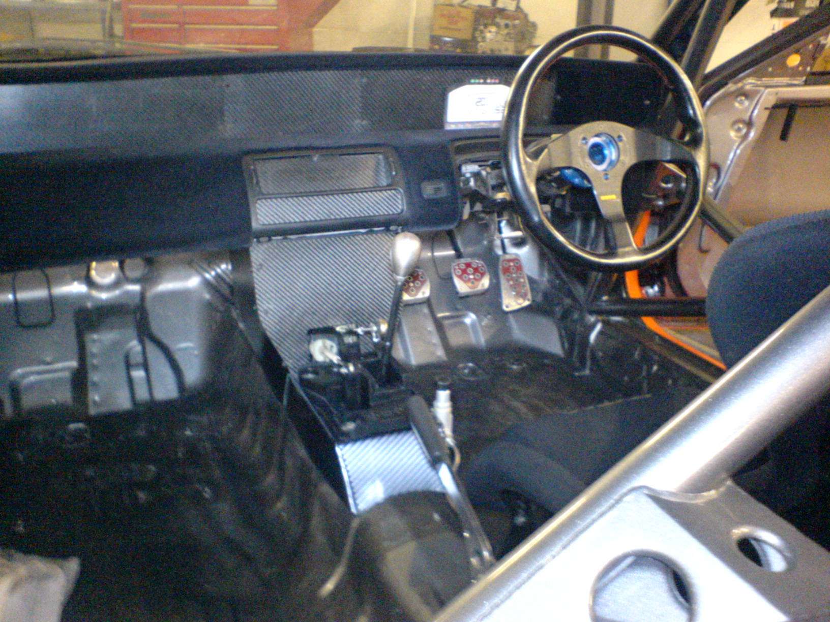
Cables attached to check operation. Note from this shot how high and close to the steering wheel the shifter now is.

Image


With the shifter finalised and the cables attached I could then get on with finishing off the last parts of the dash panels. Here you can see the lower facia panel and side panels trimmed around the gear shifter and mount.

Image


Carbon side panels added to facia to enclose the whole lower dash mounting system for improved looks and protection to the systems and wiring that can be installed here - most likely the ECU will be enclosed behind here

Image

Image


Full dash and facias...Done - Well apart from the instruments, switches and safety systems that need to be installed. Hmmmm need to do something about those red bits in the pedals as well !!

Image


Cheers
Rich
Last edited by Buzzonion Vtec on Sun Jan 29, 2012 10:57 pm, edited 1 time in total.

User avatar
Buzzonion Vtec
Posts: 214
Joined: Sat Jan 28, 2012 10:29 am
My Generation: 4G

Coil-on-plug - Groundwork

Post by Buzzonion Vtec » Sun Jan 29, 2012 9:33 pm

Update 20 – Originally Posted - Mon Aug 30, 2010 10:33 pm

http://preludeuk.forumup.com/viewtopic. ... =preludeuk

Update continued...

Coil on Plug conversion

Ok so it's already been discussed a bit in this thread and I've already mentioned that it's not 100% complete but as I've been asked several times I figured I might as well post the pics up of the work so far.
Bear in mind that this won't be 100% finished until the motor is fully back together, dedicated engine loom put together, Motec installed and car wired up. Quite a bit to do obviously but the basics are done and it's now just really a matter of configuring and wiring...no big deal.


I wanted to do this conversion with all Honda sensors and coils simply because they are easy to get hold of and I have a load of spare items already. There are other ways to go about this and some bits commercially available but why buy when you can make?


First off I decided to go with the nice and clean crank trigger system designed by Honda rather than some kind of aftermarket toothed trigger wheel. So here we have a H22a7 oil pump complete with mounting bosses for the sensors.

Image


TDC sensor left, CKP sensor right. These factory sensors will be used in conjunction with the Motec ECU. They also will allow for distributorless Coil-on-Plug ignition conversion

Image


Spare cylinder head. This is (as I'm sure we are aware) how a stock H22 head looks with standard distributor and HT lead ignition.

Image


H22a7 distributor fully stripped. Note - the A7 still has an internal coil and ignitor but only has one sensor (compared to 3 in a normal H22 dizzy). This sensor (cam position CMP) and trigger are required for this conversion but the rest can be discarded.

Image


H22a7 dizzy shell complete with CMP sensor trigger. As this is the only part I wish to re-use I figured we can loose some size and excess from the dizzy.

Image


Bottom removed from dizzy. This used to house the coil

Image


More slimming and trimming to come

Image


CMP sensor and trigger in place. The material above can be removed to slim the sensor housing right down.

Image


All that remains of the original dizzy now is the CMP and trigger housing.

Image


Shaft bearing housing requires some trimming to sit flush and low enough over the CMP and trigger

Image


Drive shaft now cut to length

Image


The component parts to what is now just a cam position sensor/trigger

Image


Cam sensor/trigger assembled

Image


Nice, snug and compact. Assembly now needs a cover to protect the internals

Image


Fabricated alloy cover plate

Image


Wiring harness and plug routed discretely under the cam trigger housing

Image


The completed cam trigger assembly mounted onto head

Image

Image


This pic show the cam trigger in place along with the 4 ignition coils that will be used. These are Honda DC5 items which fit a treat

Image


Finally a lick of paint for the cam trigger assembly

Image

Image


Unfortunately that's as much as I can give you on the COP conversion for now, anyway most of the rest of it is literally going to be config and wiring stuff and that's gonna be a little way off yet.


Rich
:D
Last edited by Buzzonion Vtec on Sun Jan 29, 2012 10:59 pm, edited 1 time in total.

User avatar
Buzzonion Vtec
Posts: 214
Joined: Sat Jan 28, 2012 10:29 am
My Generation: 4G

Re: Thread Building - Please don't reply just yet ;-)

Post by Buzzonion Vtec » Sun Jan 29, 2012 9:34 pm

REPLY


There we go then... blimey that was hard work !!!
5 Updates in one evening !!!!!! I must be mad :lol:

That's where we are with it all at the moment. There have been other minor advances in other areas and some other work being done off the car but no point updating any of that until it's finished and ready to show.

The next update may be a little while away now as I also have another race car build on the go !! This one is much more of a get it built in a hurry kind of car with very few of the nice touches that the Lude enjoys. The plan is to get the new car done quickly so I can enjoy some track time more regularly again...that should keep the encouragement and enthusiasm up for this build and it will also stop me from rushing it through to completion which I know I would always regret if I did.

Cheers for always for taking an interest

Rich

Post Reply

Return to “Lude Profiles”